SEL-751
Feeder Protection Relay
The SEL-751 is the right solution for industrial and utility feeder protection, with conventional/low-energy analog (LEA) current and voltage input support, flexible I/O options, easy mounting, and fast settings.
The SEL-751 provides complete protection for radial and looped distribution circuits. It offers arc-flash mitigation, fault location, high-impedance fault detection, broken conductor detection, event analysis, and more. You can quickly integrate the relay into serial- or Ethernet-based communications with IEC 61850 Edition 2.1, IEC 60870-5-103, the IEC 62439 Parallel Redundancy Protocol (PRP), EtherNet/IP, the Rapid Spanning Tree Protocol (RSTP), the IEEE 1588 Precision Time Protocol (PTP), Modbus, DNP3, and other protocols.
Starting At
$1,310Feeder Protection—Protect radial and looped distribution circuits with comprehensive protection capabilities, including time-overcurrent, directional overcurrent, autoreclosing, over-/undervoltage, frequency, second- and fifth-harmonic blocking, optional LEA voltage inputs, IEC cable/line thermal element, islanding detection, and much more.
LEA Sensor Inputs—Apply the SEL-751 in medium- and low-voltage applications that use low-energy current/voltage sensors. LEA sensors for measurement of primary voltages and currents are gaining popularity owing to their excellent linearity and wide dynamic range characteristics, reduced size, reduced weight, and enhancement of personnel safety. The LEA current/voltage input card supports three current channels, Rogowski coil or low-power current inputs, three LEA voltage sensor inputs, and one 200 mA neutral input. The LEA current and voltage channels accept an RJ45 connector input, and the 200 mA neutral channel accepts a terminal block input.
Sensitive Neutral Input—Using the directional control capability, protect high-impedance grounded, ungrounded, and Petersen coil-grounded systems in relays with the 200 mA neutral current input option. The 200 mA neutral input option is also used for nondirectional SEF protection.
Arc-Flash Mitigation—Improve safety for personnel with optional arc-flash detection capabilities. The SEL-751 offers combined light and high-speed overcurrent detection for arc-flash events. This combination provides the ideal solution for speed and security.
High-Impedance Fault Detection—Detect downed conductors, even on poorly conducting surfaces, with Arc Sense technology (AST). AST algorithms detect arcing produced by some high-impedance faults and will alarm or trip the breaker. This technology provides an added level of protection over conventional feeder protection methods.
Reliable Protection in Harsh Environments—The SEL-751 operates in extreme conditions, with an operating temperature of –40° to +85°C (–40° to +185°F), and it is designed and tested to exceed applicable standards, including vibration, electromagnetic compatibility, and adverse environmental conditions. In addition, the SEL-751 is ATEX-certified and Underwriters Laboratories (UL) Class I, Division 2-certified for use in hazardous and potentially explosive environments.
Automation and Control—Apply the SEL-751 on feeders and provide protection, automation, and control capabilities all in one package.
Event Analysis—Conduct post-event analysis more efficiently with the detailed event records that are available in the SEL-751. Combine oscillographic and digital information to find root cause. Add a satellite-synchronized time source, like the SEL-2401, SEL-2407, or SEL-2488 Satellite-Synchronized Clocks, for convenient alignment of event information from multiple devices.
Situational Awareness—Improve situational awareness and asset utilization with IEEE C37.118 synchrophasor measurements.
Fault Location—Find faults faster and restore service more quickly with fault location algorithms. Communicate fault location information automatically to a control center by using serial or Ethernet communications and SCADA protocols.
Features
- Front—LCD Version
- Front—Touchscreen Version
- Back—Conventional CT/PT
- Back—LEA Sensor Inputs
- Touchscreen—Bay Screen
- Touchscreen—Authentication
- Touchscreen—Breaker Control
- Touchscreen—Fundamental Metering
- Touchscreen—Phasors
- Touchscreen—Energy Metering
- Touchscreen—Sequential Events Recorder
-
- 1
Large 2 × 16 character LCD
- 2
Default messages or up to 32 customizable display labels notify personnel of power system events or the relay status
- 3
Programmable front-panel tricolor LEDs
- 4
Customizable pushbuttons and labels
- 5
User-configurable label kit
- 6
Two programmable tricolor LEDs per pushbutton
123456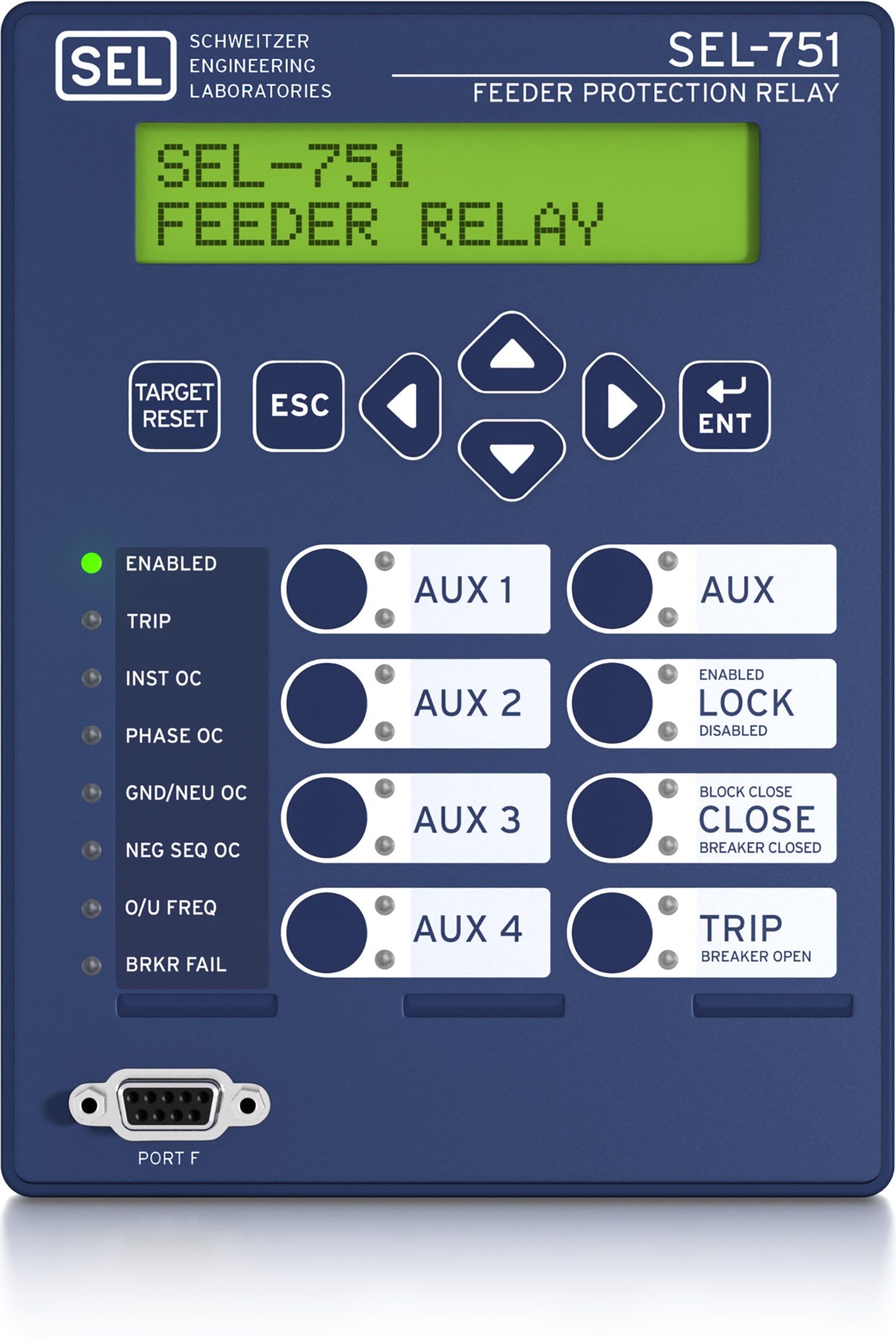
-
-
- 1
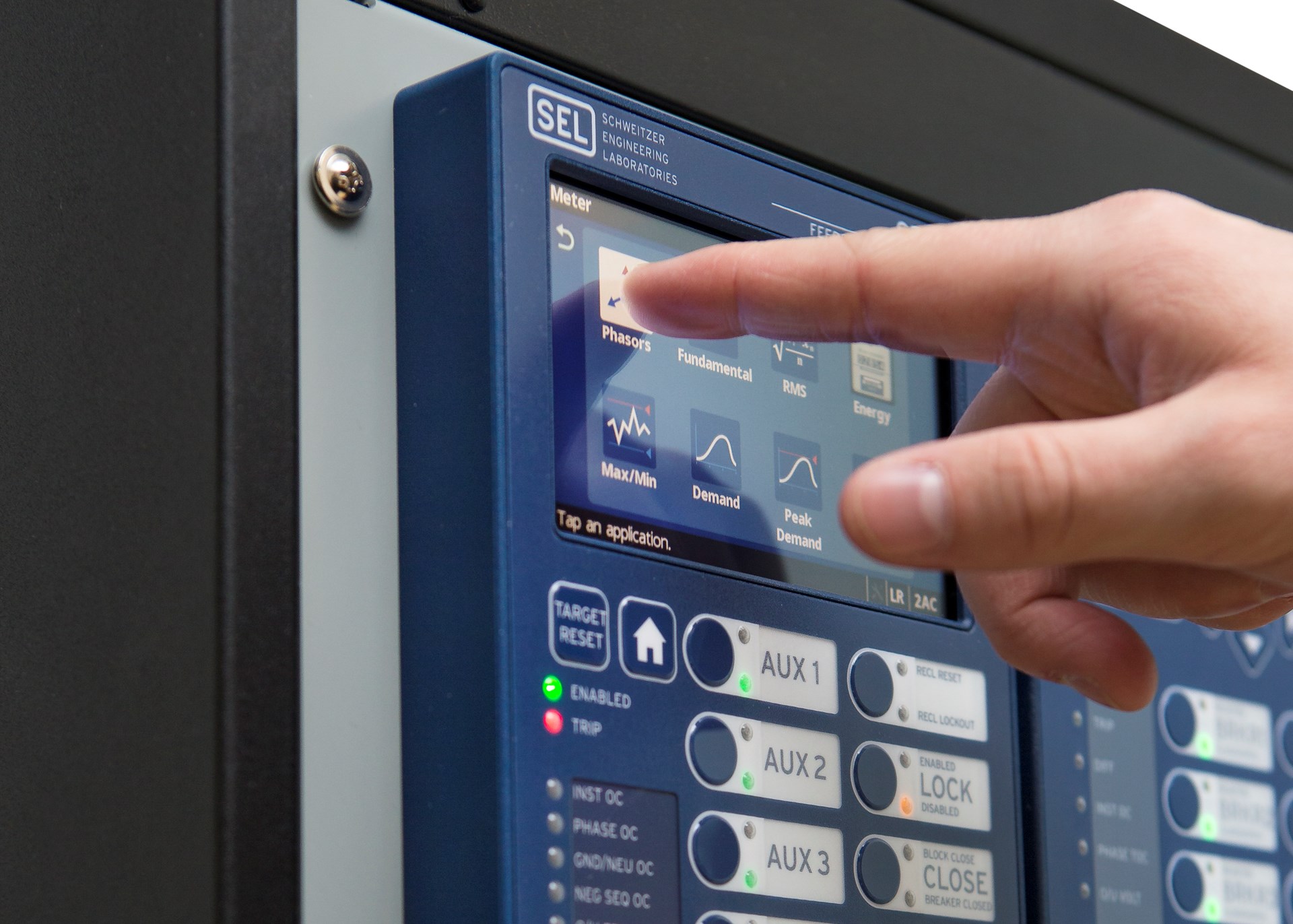
The 5-inch, 800 × 480 display offers direct navigation via a capacitive touchscreen
- 2
Folders and applications provide quick access to bay screens, metering and monitoring data, reports, settings, and more
- 3
The home pushbutton allows you to easily return to the default home screen
- 4
Programmable front-panel LEDs with user-configurable labels alert operators to faulted phases and element operation
- 5
Programmable operator pushbuttons with user-configurable labels allow front-panel customization
12345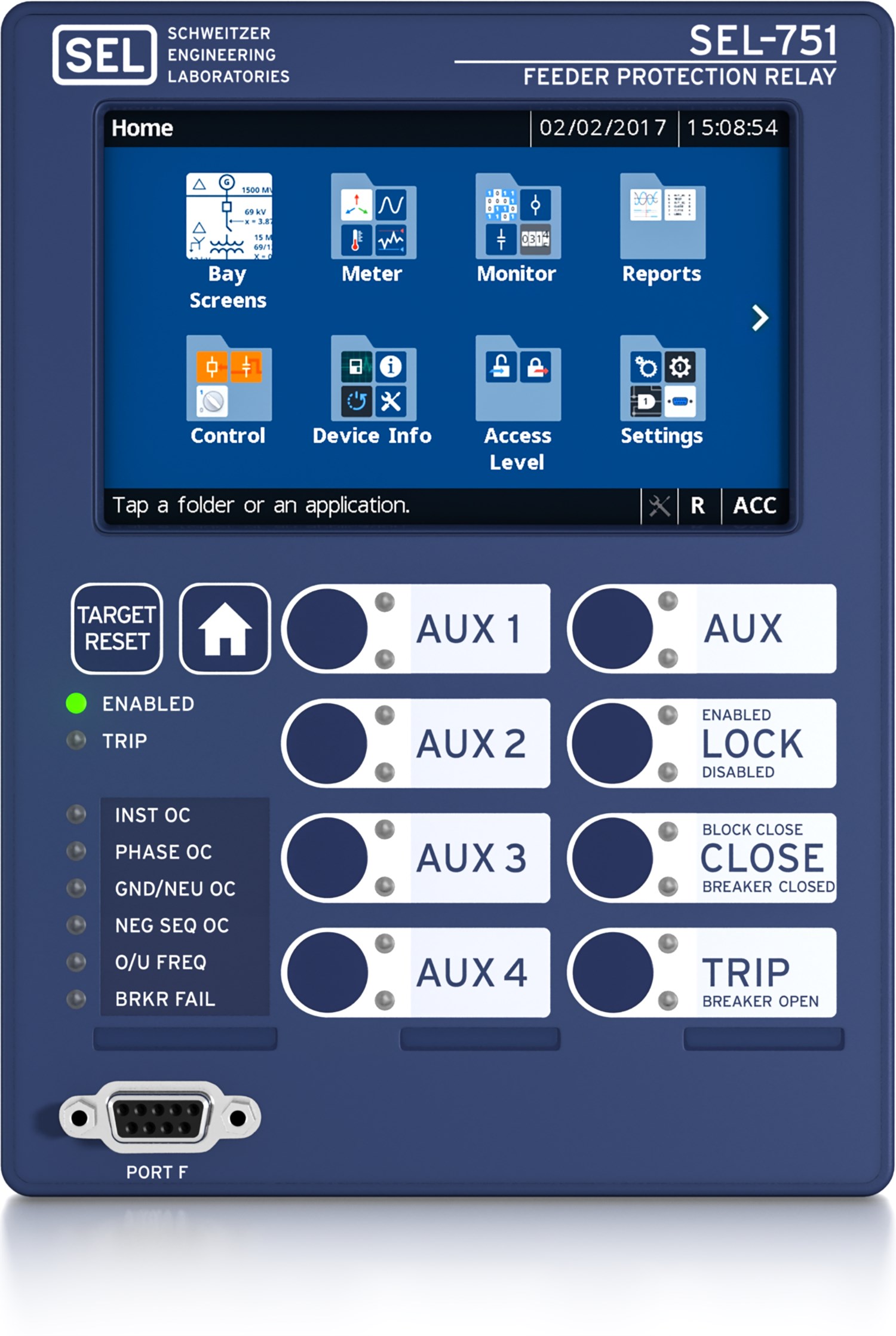
-
-
- 1
Power supply options include 110–250 Vdc/110–240 Vac or 24–48 Vdc
- 2
A variety of communications protocols and media provide flexibility to communicate with other devices and control systems
- 3
Integrated web server enables direct relay access for metering and monitoring data
- 4
The optional fiber-optic serial port provides quick and easy engineering access
- 5
Card slots include positions for optional I/O or an arc-flash detection/Vsync/Vbat card
- 6
Phase current and optional phase voltage inputs are on one card, freeing up space for additional SELect™ I/O card options
123456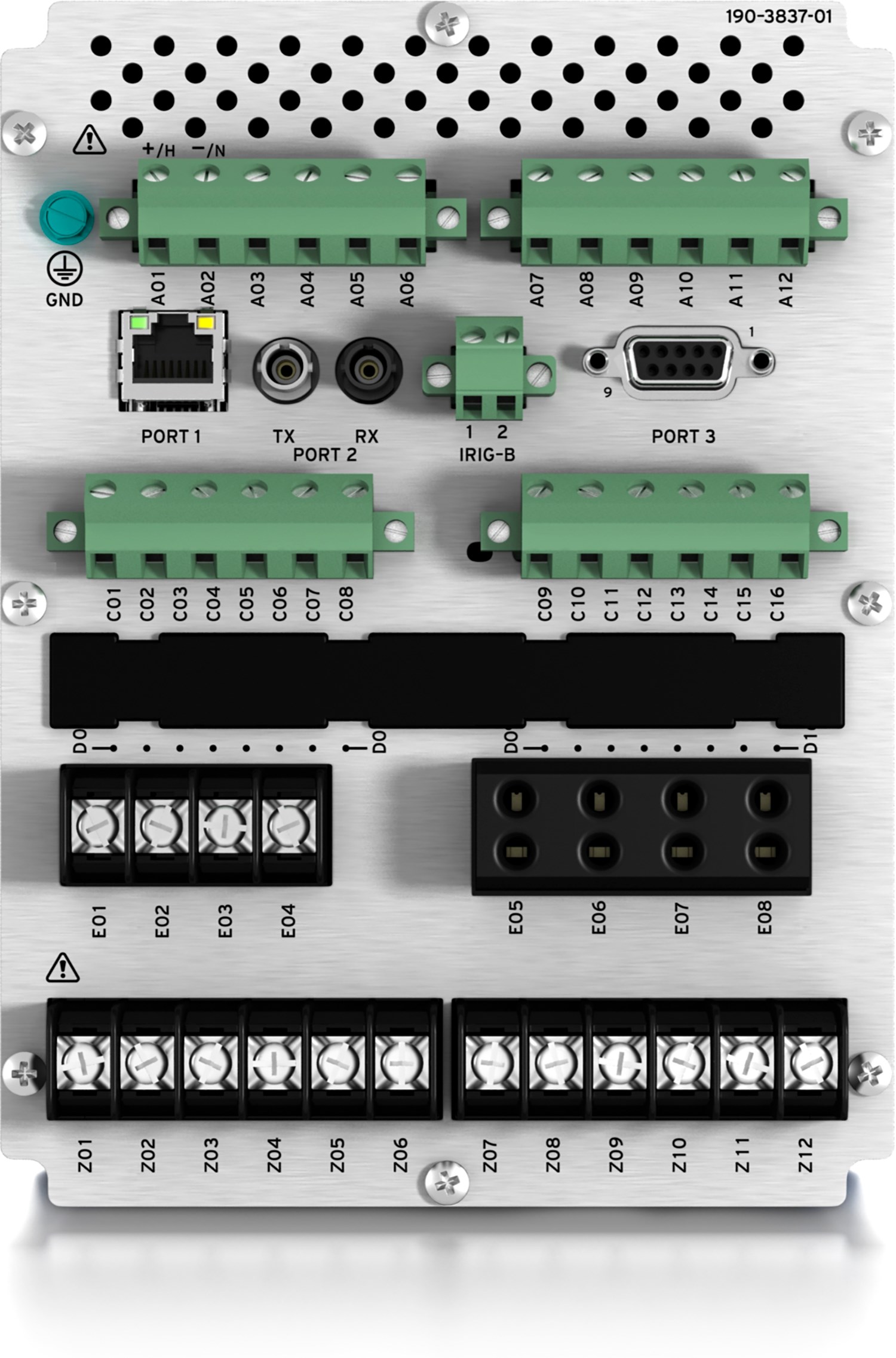
-
-
- 1
Power supply options include 110–250 Vdc/110–240 Vac or 24–48 Vdc
- 2
A variety of communications protocols and media provide flexibility to communicate with other devices and control systems
- 3
Integrated web server enables direct relay access for metering and monitoring data
- 4
The optional fiber-optic serial port provides quick and easy engineering access
- 5
Card slots include positions for optional I/O or an arc-flash detection/Vsync/Vbat card
- 6
Low-energy analog current and voltage sensor inputs (compliant with IEC 61869-6,-13 standards)
123456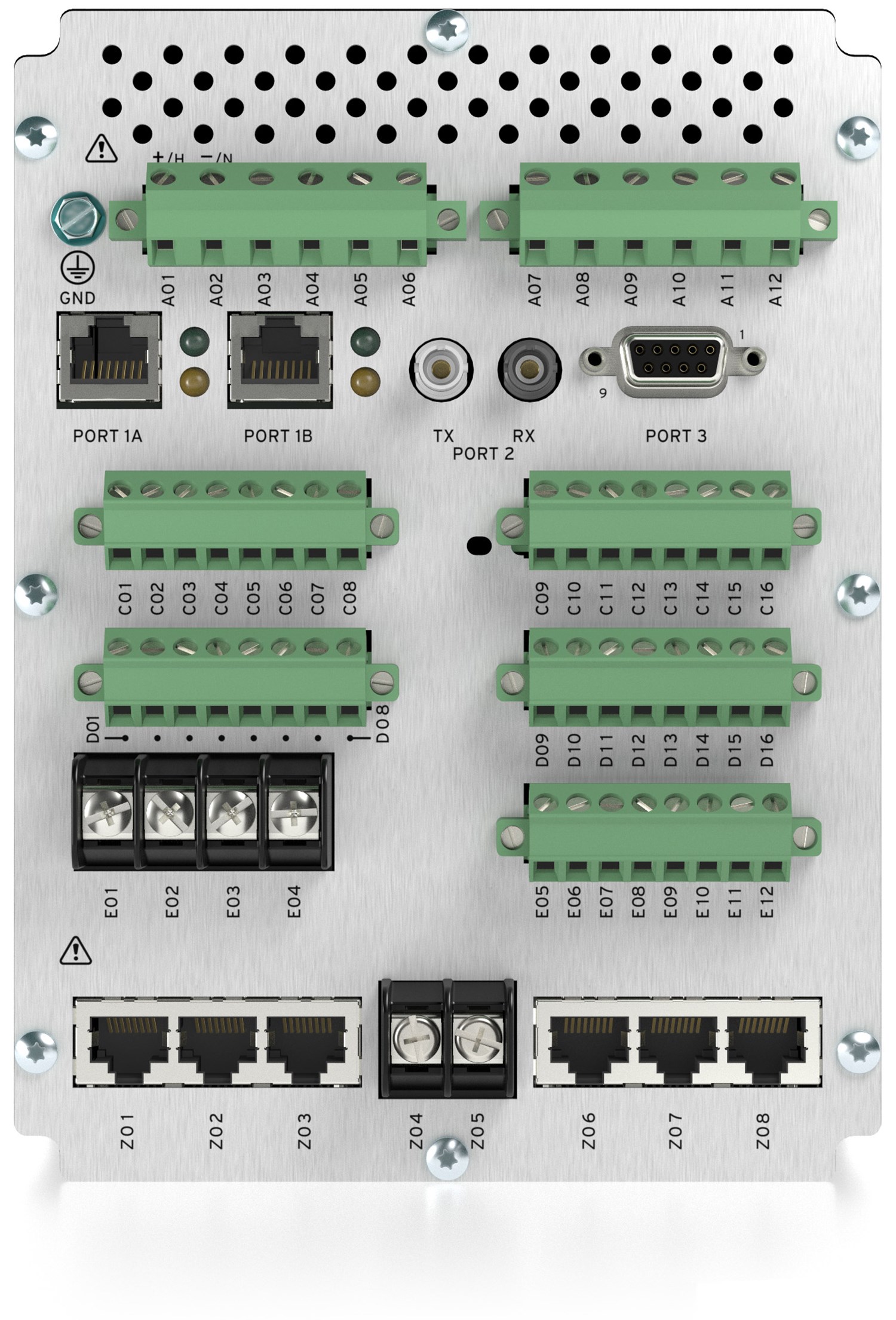
-
-
- 1
Bay Screens and Bay Control
Select from predefined bay screens, or configure as many as five custom bay screens using the acSELerator® Bay Screen Builder SEL-5036 Software and acSELerator QuickSet® SEL-5030 Software. You can control one breaker, eight two-position disconnects, and two three-position disconnects and can view analog and digital data in a contextual display.
To control a breaker or disconnect, simply tap the Bay Screens application on the home screen and then the breaker or disconnect you want to control.
1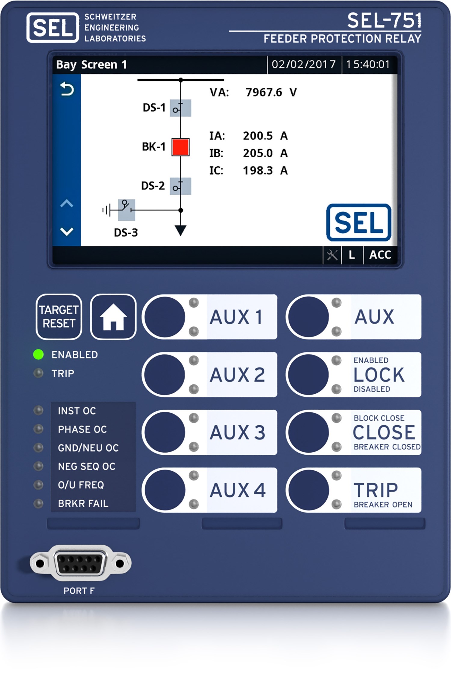
-
-
- 1
Authentication
Enter your Level 2 password and tap Submit. The onscreen keyboard allows you to quickly and easily enter passwords, search for Relay Word bits, and enter settings.
1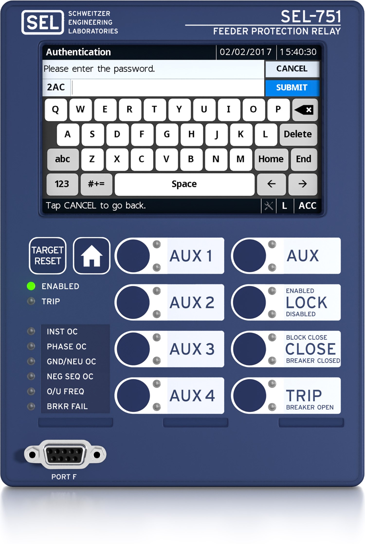
-
-
- 1
Breaker Control
Tap Trip or Close to control the breaker. When asked to confirm the action before the operation is completed, choose Yes or No.
1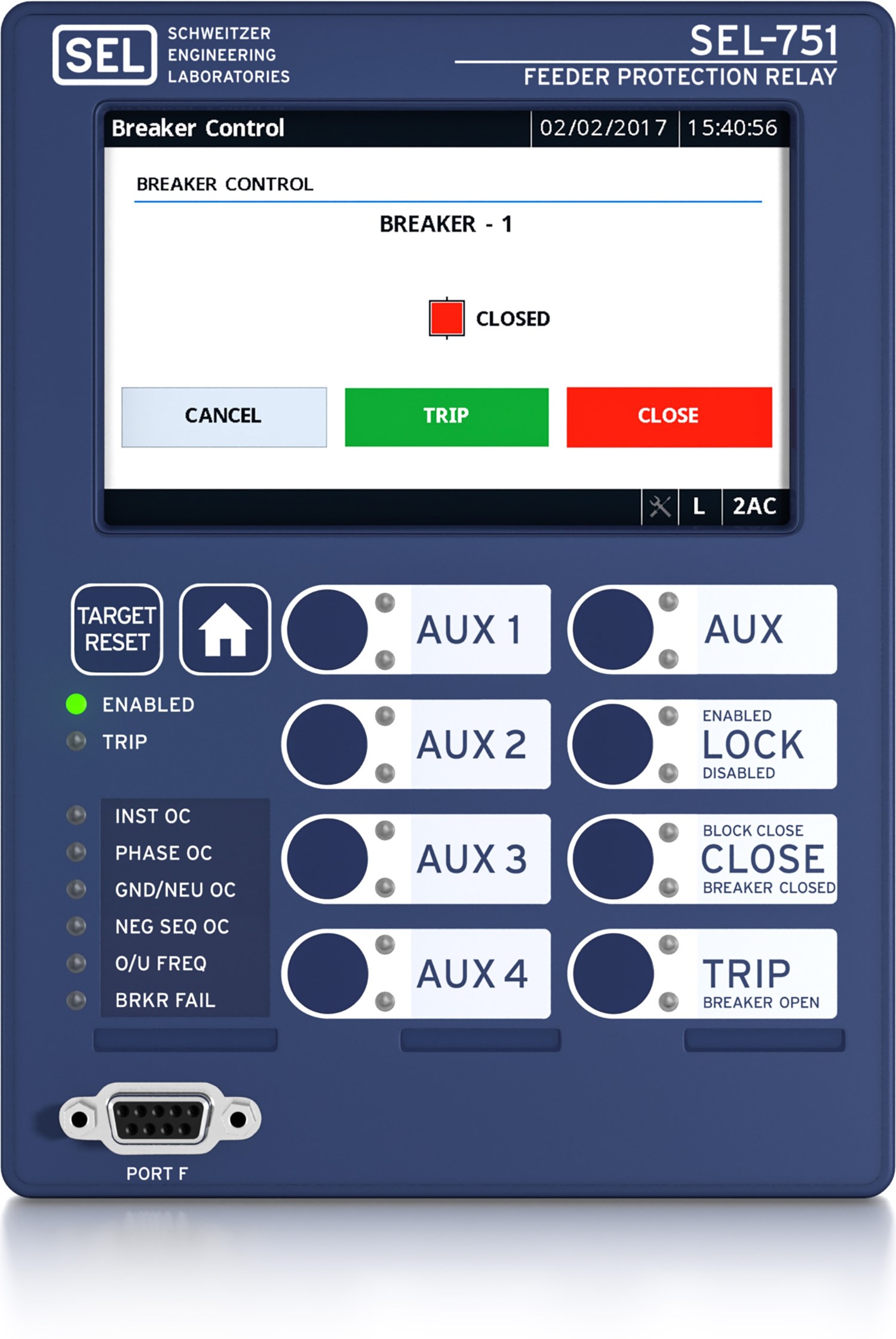
-
-
- 1
Meter Fundamentals
View the real, reactive, and apparent power of each phase in your system, and monitor the power factor information to determine if the phase current leads or lags the phase voltage.
1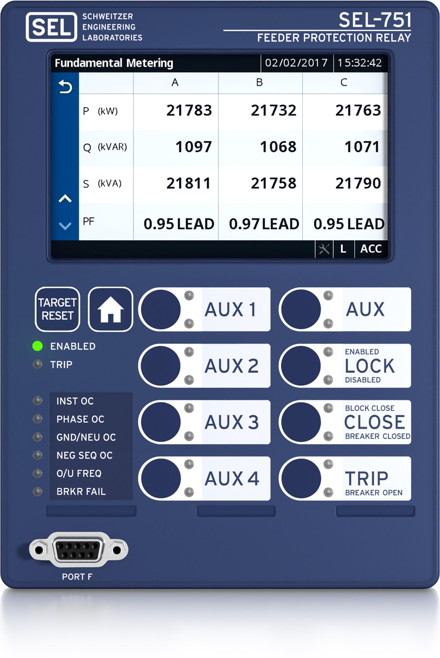
-
-
- 1
Meter Phasors
View a graphical and textual representation of the real-time voltages and currents in a power system during balanced and unbalanced conditions. By analyzing the phasors, you can determine power system conditions.
1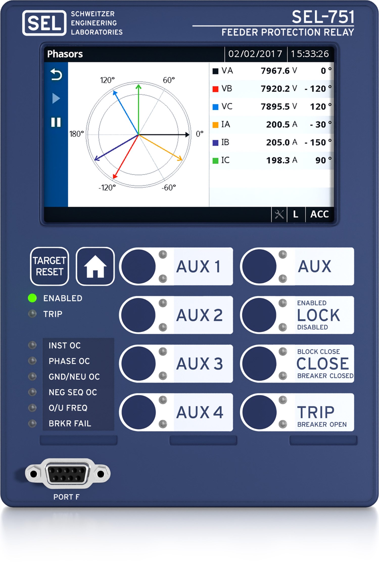
-
-
- 1
Meter Energy
Display the real, reactive, and apparent energy metering quantities imported and exported by your system. You can reset the energy values via the display and record the time and date of reset. Whether your system is a net energy producer or consumer, metered quantities accurately account for the power system energy flow.
1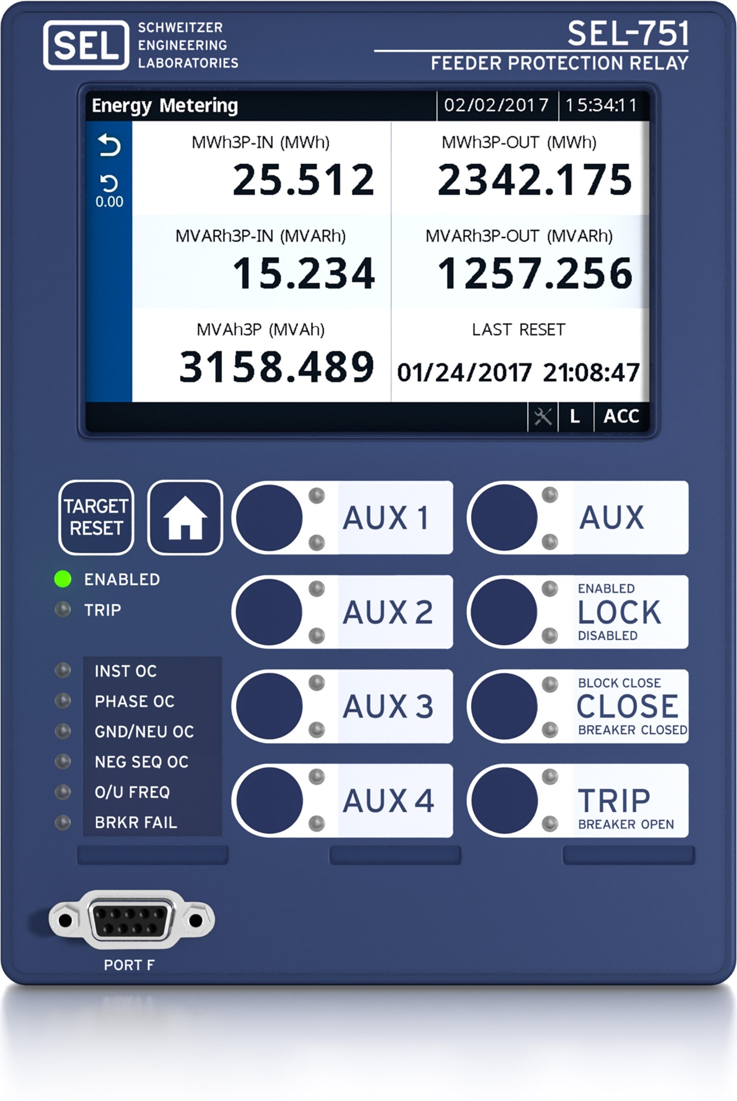
-
-
- 1
Sequential Events Recorder
Easily review the time-stamped Sequential Events Recorder (SER) data, including whether or not the Relay Word bit asserted or deasserted, during root cause analysis of an event.
1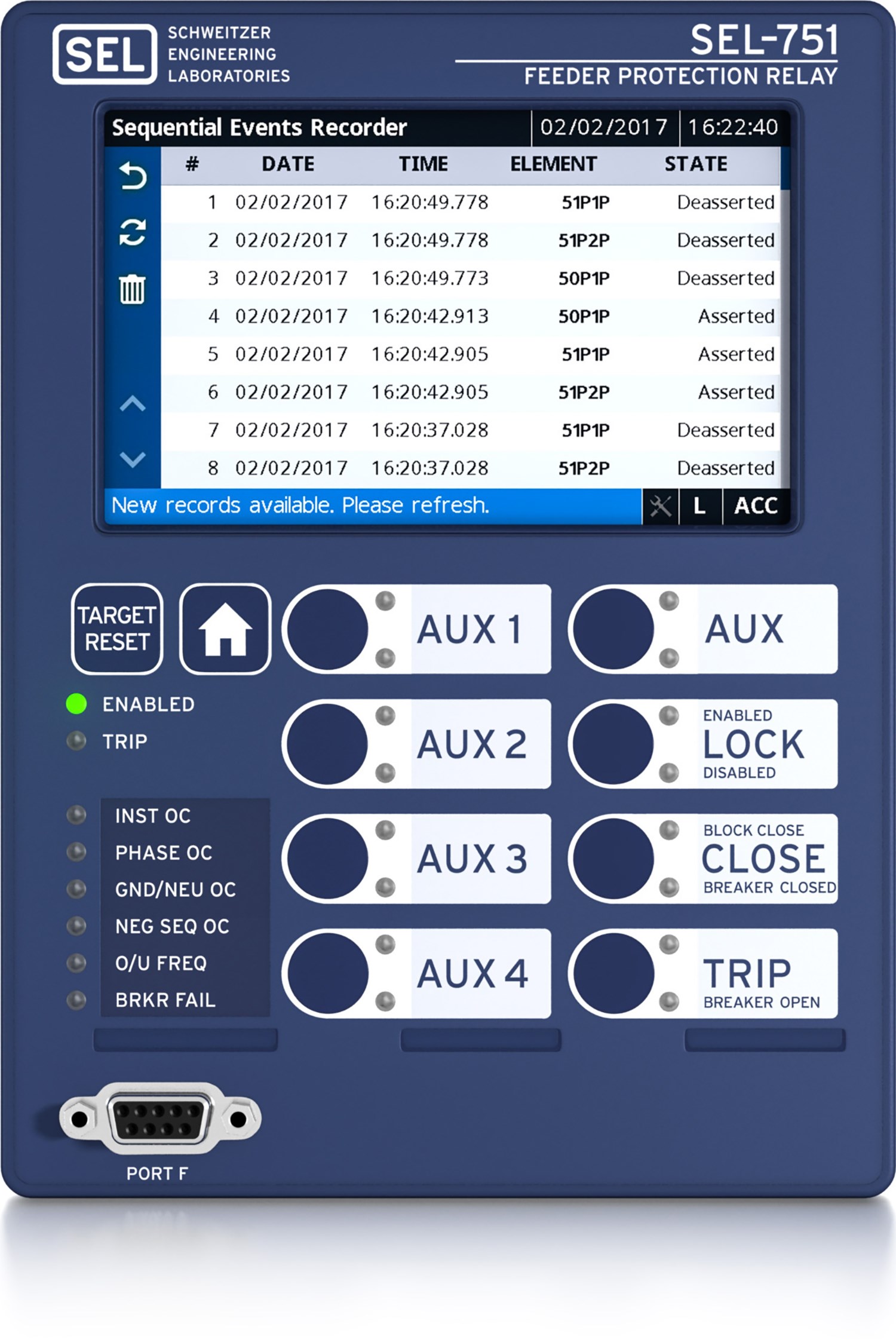
-
Details
Complete Feeder Protection
Maximize control scheme flexibility using time- and instantaneous-overcurrent, overvoltage, undervoltage, directional power, and frequency elements, with breaker failure protection for one three-pole breaker. Second- and fifth-harmonic blocking improves protection security during magnetizing inrush conditions caused by line re-energization, or by voltage recovery after an out-of-zone fault.
Optional Directional Control
Use overcurrent elements with directional control, and optimize radial and looped network protection for lines and equipment. Best Choice Ground Directional Element logic optimizes directional element performance and eliminates the need for many directional settings. The relay also supports high-impedance grounded, ungrounded, and Petersen coil-grounded systems in relays with the 200 mA neutral current transformer option. The 200 mA CT option can also be used for nondirectional SEF protection.
Optional Protection Features
Use the SEL-751 with the voltage inputs and arc-flash detection options to provide synchronism check, dc station battery monitoring, and arc-flash detection. The SEL-751 supports an option card that includes the Vsync/Vbat with 7 digital inputs or 4 arc-flash inputs. LEA currents and voltage input card supports voltage sensor inputs and Rogowski coil or low-power current transformer (LPCT) inputs for small enclosure installations.
Incipient Fault Detection
Identify potential cable failures to extend asset life and minimize unexpected downtime. The SEL-751 checks for self-extinguishing half-cycle faults, which provides an indication of imminent cable failures.
Cold-Load Pickup Element
Cold-load pickup is the phenomenon that takes place when a distribution circuit is reenergized following an extended outage of that circuit. It can result in current levels that are significantly higher than normal peak load levels. This excess amount of current draw could be falsely identified as an overcurrent condition by the relay. The cold-load pickup element identifies possible cold-load pickup events per the settings in a distribution line after an outage.
Thermal Element
Protect cables and cable insulation against thermal damage using the IEC line/cable thermal (49) element.
Optional Vector Shift
Detect islanding conditions and prevent damage to local generation by detecting voltage angle shifts upon loss of bulk generation.
Open-Conductor Detection
Apply the SEL-751 to detect and isolate open conductors. The SEL-751 incorporates phase discontinuity detection and optional broken conductor detection to provide a reliable solution for open-conductor faults that convert to high-impedance faults.
Optional High-Impedance Fault Detection
Apply the SEL-751 with AST to detect many high-impedance faults, a common result of a downed conductor. Alarm or trip for faults that produce low fault current and are undetectable with conventional relays.
Optional Touchscreen Display
The easy-to-use touchscreen interface provides a one-line mimic display for bay control and monitoring. View metered quantities, phasor diagrams, relay settings, event summaries, target statuses, Sequential Events Recorder (SER) data, and more. Extensive testing shows that the robust capacitive touchscreen display meets or exceeds industry standards as well as SEL quality and reliability requirements.
Easy Communications
Choose from Ethernet or serial communications and several protocols, including IEC 60870-5-103, Mirrored Bits communications, EtherNet/IP, IEEE 1588 PTP, and IEC 61850. Pick multiple sessions of Modbus TCP, Modbus RTU, DNP3 LAN/WAN, or DNP3 serial for custom configuration of your applications. When dual-Ethernet ports are selected, the relay also supports RSTP, IEC 62439 PRP, and Fast Failover Switching.
IEC 61850 Edition 2.1 Communications Protocol
Combine IEC 61850, an Ethernet network, and the SEL-751 for the fastest overall performance for substation automation and control. Streamline configuration of IEC 61850-enabled relays with acSELerator Architect SEL-5032 Software. Improve security using the password authentication and session time-out features. Transfer event files in COMTRADE and CEV formats as well as CID files, settings, and reports.
IEC 61850 Test Mode
Use the IEC 61850 Test Mode to test system components in energized substations without fear of operating control output contacts.
Web Server Access
The built-in web server enables secure, remote access to the relay with password protection. You can download status reports or view metering and relay information remotely. This helps minimize trips to the relay location, saving time and money.
Accelerate Firmware Downloads
Simplify maintenance by downloading relay firmware via the Ethernet port. This also enables you to access and update all of your network relays simultaneously.
Simple Network Time Protocol (SNTP)
Simplify wiring and installation by receiving a time signal over existing Ethernet networks. SNTP makes a good backup to more accurate IRIG-B time synchronization. The 1 ms accuracy is ideal for basic time synchronization throughout a substation.
Built-In IEEE C37.118 Synchrophasors
Monitor distribution networks to detect a potential cascading voltage collapse before it happens. IEEE C37.118 synchrophasors, at up to 60 messages per second, allow access to system values for wide-area monitoring and control. The IEEE C37.118 standard simplifies communication and data coordination between synchrophasor measurement units.
Expanded SELogic Control Equations
Use math and logic combinations of analog and digital values for customized applications. Adapt system control based on prefault conditions. Scale analog values and latch momentary inputs for SCADA retrieval.
Enhanced Security on Heavily Loaded Feeders
Employ load-encroachment logic to set phase overcurrent elements independently of load levels.
Flexible Design
Choose from many installation and integration options given the relay's small form factor and slide-in expansion card options.
Rugged Design
Trust the industry’s widest ambient operating temperature range, –40° to +85°C (–40° to +185°F). The SEL-751 withstands vibration, electrical surges, fast transients, and extreme temperatures, meeting stringent industry standards. A conformal-coating option for the printed circuit boards provides an additional barrier to airborne contaminants, such as hydrogen sulfide, chlorine, salt, and moisture. In addition, the SEL-751 is ATEX-certified and Underwriters Laboratories (UL) Class I, Division 2-certified for use in hazardous and potentially explosive environments.

- Simple feeder protection (currents only), including reclosing
- Electromechanical relay retrofit

- Simple feeder protection (currents only), including reclosing
- 5-inch color touchscreen display with 4 pushbuttons

- Advanced feeder protection
- 5-inch color touchscreen display with 8 pushbuttons

- Advanced feeder protection, including reclosing and directional elements
- 5-inch color touchscreen display with 8 pushbuttons
- Arc-flash mitigation
Minimum Software Version
| Product | Revision | Z Number | acSELerator QuickSet Version | SEL Grid Configurator Version |
|---|---|---|---|---|
| SEL-751 | R400-V1 | 100 | 7.1.2.0 | |
| SEL-751 | R400-V0 | 100 | 7.1.2.0 | |
| Upgrade to R400-V0 requires a new CPU card | ||||
| SEL-751 | R302-V2 | 010 | 7.0.1.0 | |
| SEL-751 | R302-V1 | 010 | 7.0.1.0 | |
| SEL-751 | R302-V0 | 010 | 7.0.1.0 | |
| SEL-751 | R301-V5 | 009 | 6.11.1.0 | |
| SEL-751 | R301-V4 | 009 | 6.11.1.0 | |
| SEL-751 | R301-V3 | 009 | 6.11.1.0 | |
| SEL-751 | R301-V2 | 009 | 6.11.1.0 | |
| SEL-751 | R301-V1 | 009 | 6.11.1.0 | |
| SEL-751 | R301-V0 | 009 | 6.11.1.0 | |
| SEL-751 | R300-V9 | 008 | 6.9.0.2 | |
| SEL-751 | R300-V8 | 008 | 6.9.0.2 | |
| SEL-751 | R300-V7 | 008 | 6.9.0.2 | |
| SEL-751 | R300-V6 | 008 | 6.9.0.2 | |
| SEL-751 | R300-V5 | 008 | 6.9.0.2 | |
| SEL-751 | R300-V4 | 008 | 6.9.0.2 | |
| SEL-751 | R300-V3 | 008 | 6.9.0.2 | |
| SEL-751 | R300-V2 | 008 | 6.9.0.2 | |
| SEL-751 | R300-V1 | 008 | 6.9.0.2 | |
| SEL-751 | R300-V0 | 008 | 6.9.0.2 | |
| SEL-751 | R202-V5 | 007 | 6.6.0.0 | |
| SEL-751 | R202-V4 | 007 | 6.6.0.0 | |
| SEL-751 | R202-V3 | 007 | 6.6.0.0 | |
| SEL-751 | R202-V2 | 007 | 6.6.0.0 | |
| SEL-751 | R202-V1 | 007 | 6.6.0.0 | |
| SEL-751 | R202-V0 | 007 | 6.6.0.0 | |
| SEL-751 | R201-V1 | 007 | 6.6.0.0 | |
| SEL-751 | R201-V0 | 007 | 6.6.0.0 | |
| SEL-751 | R200-V4 | 007 | 6.6.0.0 | |
Videos
Video Playlists
How to Set SEL-751 Video Series
- How to Set SEL-751—Part 1: Communications
- How to Set SEL-751—Part 2: Overcurrent and Time-Overcurrent Protection
- How to Set SEL-751—Part 3: Event Analysis
Latest Firmware Versions
There are no firmware versions available for this product.
| Product | Revision | Firmware ID | Date Available | Serial Number |
|---|---|---|---|---|
| SEL-751 | R402-V1 | SEL-751-R402-V1-Z102100-D20250701 | 7/11/25 | ~3251920001 |
| SEL-751 | R401-V4 | SEL-751-R401-V4-Z101100-D20250701 | 7/11/25 | ~3251920001 |
| SEL-751 | R400-V6 | SEL-751-R400-V6-Z100100-D20250701 | 7/11/25 | ~3251920001 |
| SEL-751 | R302-V7 | SEL-751-R302-V7-Z010005-D20250214 | 3/27/25 | ~3250860001 |
The Firmware IDs for older versions of the firmware can typically be found in Appendix A of the instruction manual.
Minimum Software Version
| Product | Revision | Z Number | acSELerator QuickSet Version | SEL Grid Configurator Version |
|---|---|---|---|---|
| SEL-751 | R400-V1 | 100 | 7.1.2.0 | |
| SEL-751 | R400-V0 | 100 | 7.1.2.0 | |
| Upgrade to R400-V0 requires a new CPU card | ||||
| SEL-751 | R302-V2 | 010 | 7.0.1.0 | |
| SEL-751 | R302-V1 | 010 | 7.0.1.0 | |
| SEL-751 | R302-V0 | 010 | 7.0.1.0 | |
| SEL-751 | R301-V5 | 009 | 6.11.1.0 | |
| SEL-751 | R301-V4 | 009 | 6.11.1.0 | |
| SEL-751 | R301-V3 | 009 | 6.11.1.0 | |
| SEL-751 | R301-V2 | 009 | 6.11.1.0 | |
| SEL-751 | R301-V1 | 009 | 6.11.1.0 | |
| SEL-751 | R301-V0 | 009 | 6.11.1.0 | |
| SEL-751 | R300-V9 | 008 | 6.9.0.2 | |
| SEL-751 | R300-V8 | 008 | 6.9.0.2 | |
| SEL-751 | R300-V7 | 008 | 6.9.0.2 | |
| SEL-751 | R300-V6 | 008 | 6.9.0.2 | |
| SEL-751 | R300-V5 | 008 | 6.9.0.2 | |
| SEL-751 | R300-V4 | 008 | 6.9.0.2 | |
| SEL-751 | R300-V3 | 008 | 6.9.0.2 | |
| SEL-751 | R300-V2 | 008 | 6.9.0.2 | |
| SEL-751 | R300-V1 | 008 | 6.9.0.2 | |
| SEL-751 | R300-V0 | 008 | 6.9.0.2 | |
| SEL-751 | R202-V5 | 007 | 6.6.0.0 | |
| SEL-751 | R202-V4 | 007 | 6.6.0.0 | |
| SEL-751 | R202-V3 | 007 | 6.6.0.0 | |
| SEL-751 | R202-V2 | 007 | 6.6.0.0 | |
| SEL-751 | R202-V1 | 007 | 6.6.0.0 | |
| SEL-751 | R202-V0 | 007 | 6.6.0.0 | |
| SEL-751 | R201-V1 | 007 | 6.6.0.0 | |
| SEL-751 | R201-V0 | 007 | 6.6.0.0 | |
| SEL-751 | R200-V4 | 007 | 6.6.0.0 | |
Sales Resource Central access is required to view the content in this tab.
Sales Resource Central751 - Software Tab
Configuration
acSELerator QuickSet SEL-5030 Software
QuickSet is a tool for engineers and technicians to quickly and easily configure, commission, and manage power system devices. QuickSet includes a Graphical Logic Editor and a device template tool to reduce configuration time and streamline deployment.
Learn more and download on the QuickSet software page.
acSELerator Architect SEL-5032 Software
Architect allows users to configure and document IEC 61850 systems that include GOOSE, Sampled Values (SV), or Manufacturing Message Specification (MMS) communications. Architect automatically compares SCL files with IEC 61850 requirements to ensure standard compliance.
Learn more and download on the Architect software page.
Automated Data Collection
SEL Data Management and Automation (DMA) Application Suite
Available on the Blueframe platform, DMA applications automatically collect, store, and manage device-specific information like oscillography, Sequence of Events (SOE) data, device settings, and property information. They also provide automated password rotation and streamlined device audits.
Learn more on the DMA software page.
Visualization and Analysis
SEL-5601-2 synchroWAVe Event Software
synchroWAVe Event helps engineers diagnose a protective relay’s behavior during a power system fault. It is a powerful and easy-to-use solution for displaying and analyzing SEL relay event reports and COMTRADE files.
Learn more and download on the synchroWAVe Event software page.
