
SEL-710-5
Motor Protection Relay
Protect asynchronous (induction) and synchronous motors with one SEL-710-5 Motor Protection Relay. Features include broken rotor bar detection and variable-frequency drive (VFD) support as well as options for arc-flash detection (AFD), differential protection, and synchronous motor protection. The synchronous option supports power factor regulation and includes, at no additional cost, a voltage divider accessory to interface with the motor excitation system.
An optional 5-inch, 800 × 480 color touchscreen display allows you to directly set, monitor and control your system, including up to five two- or three-position disconnect switches. You can quickly integrate the SEL-710-5 into serial-or Ethernet-based communications schemes with IEC 61850 Edition 2, IEC 60870-5-103, the IEC 62439 Parallel Redundancy Protocol (PRP), Mirrored Bits communications, Modbus, DNP3, EtherNet/IP, the Rapid Spanning Tree Protocol (RSTP), the IEEE 1588 Precision Time Protocol (PTP), and other protocols. Together with the AccuTrack Thermal Model, these features provide a great solution for all of your motor protection applications.
Starting At
$4,060Motor Protection—Protect a full range of low- or medium-voltage, three-phase induction and synchronous motors. The slip-dependent thermal model (AccuTrack) allows independent thermal protection of both the rotor and stator.
Arc-Flash Mitigation—Select optional arc-flash detection (AFD) inputs for overcurrent-supervised arc-flash protection. Reduce incident energy further by selecting high-speed, high-current interrupting output contacts to achieve secure, reliable, and fast arc-flash tripping.
Differential Protection—Configure current differential elements for more comprehensive protection of large, high-value motors.
Broken Rotor Bar Detection—Detect broken rotor bars in squirrel-cage induction motors by implementing the optional spectrum analysis features. Minimize repair costs and downtime by detecting rotor bar problems before they cause catastrophic motor failure.
Reliable Protection in Harsh Environments—The SEL-710-5 operates in extreme conditions, with an operating temperature of –40° to +85°C (–40° to +185°F), and it is designed and tested to exceed applicable standards, including vibration, electromagnetic compatibility, and adverse environmental conditions. In addition, the SEL-710-5 is ATEX-certified and Underwriters Laboratories (UL) Class I, Division 2-certified for use in hazardous and potentially explosive environments.
Synchronous Motors—Protect synchronous motors (brush and brushless). Use the optional inputs for measuring and controlling excitation system signals on brushed motors. Regulate power factor using digital or analog outputs of the relay connected directly to the excitation system.
Front-Panel Flexibility—Improve functional control and situational awareness with the programmable auxiliary buttons, LEDs, and configurable labels.
Metering and Monitoring—Analyze SER reports and oscillographic event reports for rapid commissioning, testing, and post-fault diagnostics. Use the SEL-710-5 Relay’s motor start report, motor start trending, load profile monitoring, motor operating statistics, and demand metering features to reduce separately mounted metering/monitoring devices.
Flexible Communications—Choose from single or dual ports, copper or fiber-optic Ethernet or serial communications, and several protocols, including IEC 61850 Edition 2, EtherNet/IP, Rapid Spanning Tree Protocol (RSTP), IEC 60870-5-103, IEEE 1588 PTP, PRP, Mirrored Bits communications, DNP3 serial, and DNP3 LAN/WAN. You can select from multiple Modbus TCP or Modbus serial sessions for custom configuration of your application.
Asset Monitoring—Reduce production losses from unexpected equipment failures and lower maintenance costs by switching to predefined maintenance schedules. The SEL-710-5 can track the operating characteristics of your motor and accompanying devices with the built-in asset monitoring capability. You can monitor items such as vibration, motor start current, motor start times, motor stop times, broken rotor bars, incipient cable faults, and excessive wear on molded-case circuit breakers.
LEA Sensor Inputs—The SEL-710-5 can be ordered with low-energy analog (LEA) inputs to support medium- and low-voltage applications that use low-energy voltage sensors and Rogowski coils or other low-power current sensors. Order your device with the combination of LEA current and voltage inputs that suits your application.
Features
- Front—LCD Version
- Front—Touchscreen Version
- Back—Conventional CT/PT
- Back—LEA Sensor Inputs
- Touchscreen—Motor Control
- Touchscreen—Authentication
- Touchscreen—Start Motor
- Touchscreen—Fundamental Metering
- Touchscreen—Phasors
- Touchscreen—Vibration
- Touchscreen—Sequential Events Recorder
-
- 1
Large 2 × 16 character LCD.
- 2
Default messages or up to 32 customizable display labels notify personnel of power system events or the relay status.
- 3
Programmable front-panel tricolor LEDs.
- 4
Customizable pushbuttons and labels.
- 5
User-configurable label kit.
- 6
Two programmable tricolor LEDs per pushbutton.
123456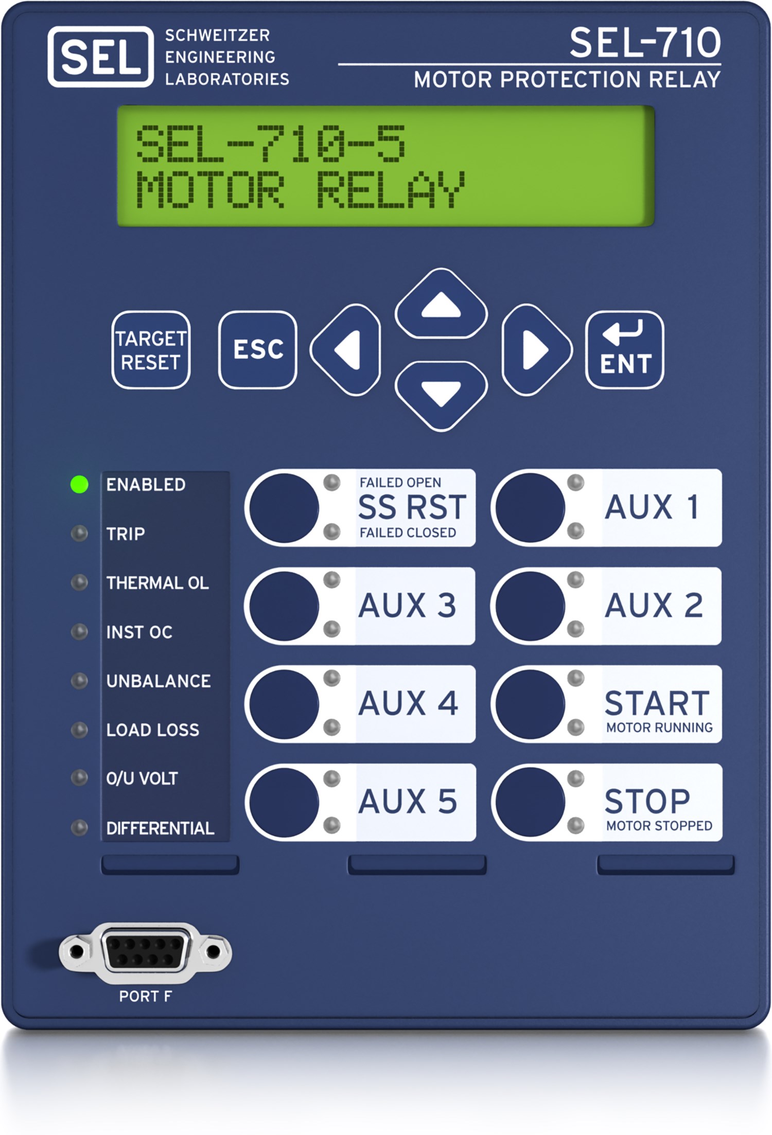
-
-
- 1
The 5-inch, 800 × 480 display offers direct navigation via a capacitive touchscreen.
- 2
Folders and applications provide quick access to bay screens, metering and monitoring data, reports, settings, and more.
- 3
Programmable front-panel LEDs with user-configurable labels alert operators to faulted phases, the relay’s status, and element operation.
- 4
Programmable operator pushbuttons with user-configurable labels allow front-panel customization.
- 5
Optional optical point sensor for AFD. Bare-fiber optical sensors are also available.
12345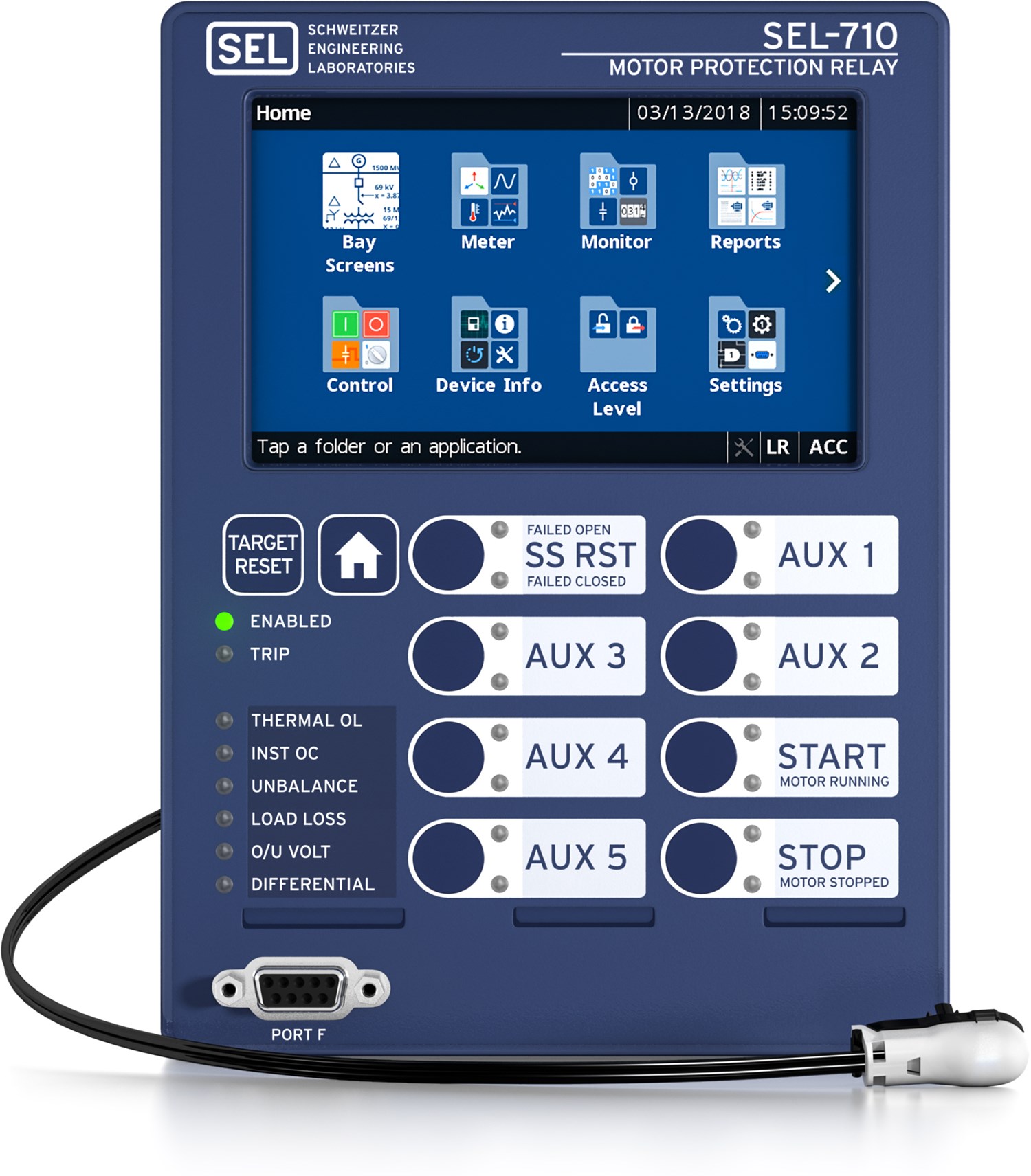
-
-
- 1
Power supply options include 110–250 Vdc/110–240 Vac or 24–48 Vdc.
- 2
An integrated web server enables direct relay access for metering and monitoring data without the need for external PC software.
- 3
A wide variety of communications protocols and media provide flexibility to communicate with other devices and control systems.
- 4
Port options include demodulated IRIG-B for precise-time input or a PTC input to protect against overcurrent conditions.
- 5
Mirrored Bits communications provides fast and reliable relay-to-relay communication.
- 6
Card slots include positions for optional I/O, arc-flash detection, or synchronous motor inputs/differential current inputs.
- 7
CT and PT inputs are located on one card, allowing for more I/O in other slots.
1234567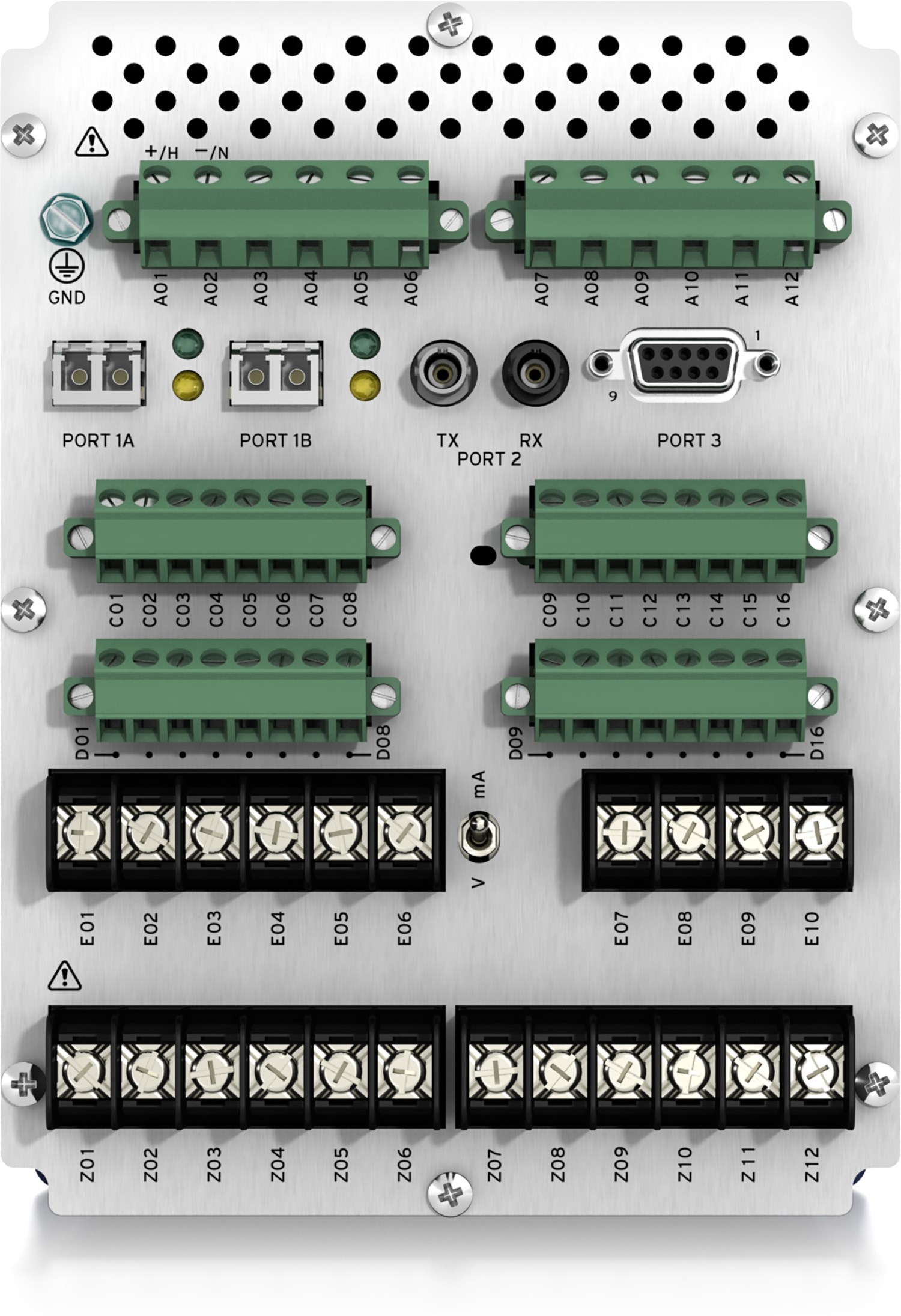
-
-
- 1
Power supply options include 24–48 Vdc or 110–250 Vdc/110–240 Vac.
- 2
Accelerate firmware downloads via the Ethernet port.
- 3
A wide variety of communications protocols and media provide flexibility to communicate with other devices and control systems.
- 4
Port options include demodulated IRIG-B for precise-time input or a PTC input to protect against overcurrent conditions.
- 5
Mirrored Bits communications provides fast and reliable relay-to-relay communication.
- 6
Card slots include positions for optional I/O, arc-flash detection (AFD), or synchronous motor inputs/differential current inputs.
- 7
LEA current and voltage sensor inputs.
1234567.jpg?n=63862454061000)
-
-
- 1
Motor Control
The color touchscreen lets you control a motor via a custom bay screen or the built-in Start Motor and Stop Motor applications in the Control folder.
To control a motor, simply tap the Control folder on the home screen, and then tap Start Motor or Stop Motor.
1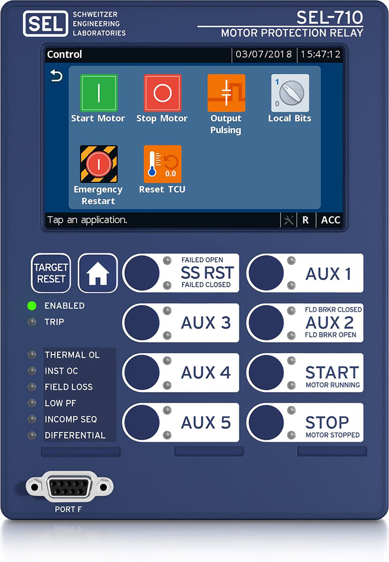
-
-
- 1
Authentication
Enter your Level 2 password and tap Submit. The onscreen keyboard allows you to quickly and easily enter passwords, search for Relay Word bits, and enter settings when necessary.
1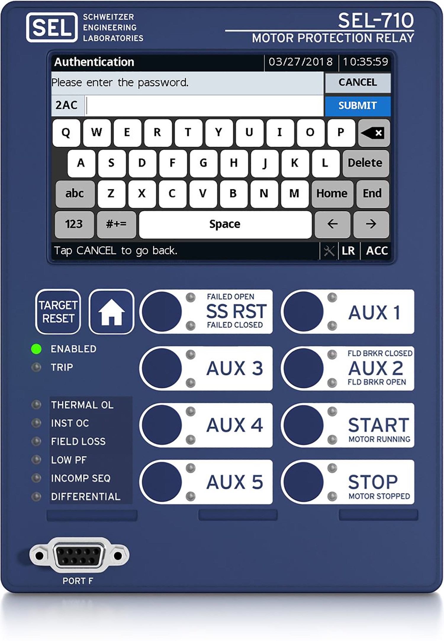
-
-
- 1
Start Motor
When the screen prompts you to confirm the action, tap Yes.
1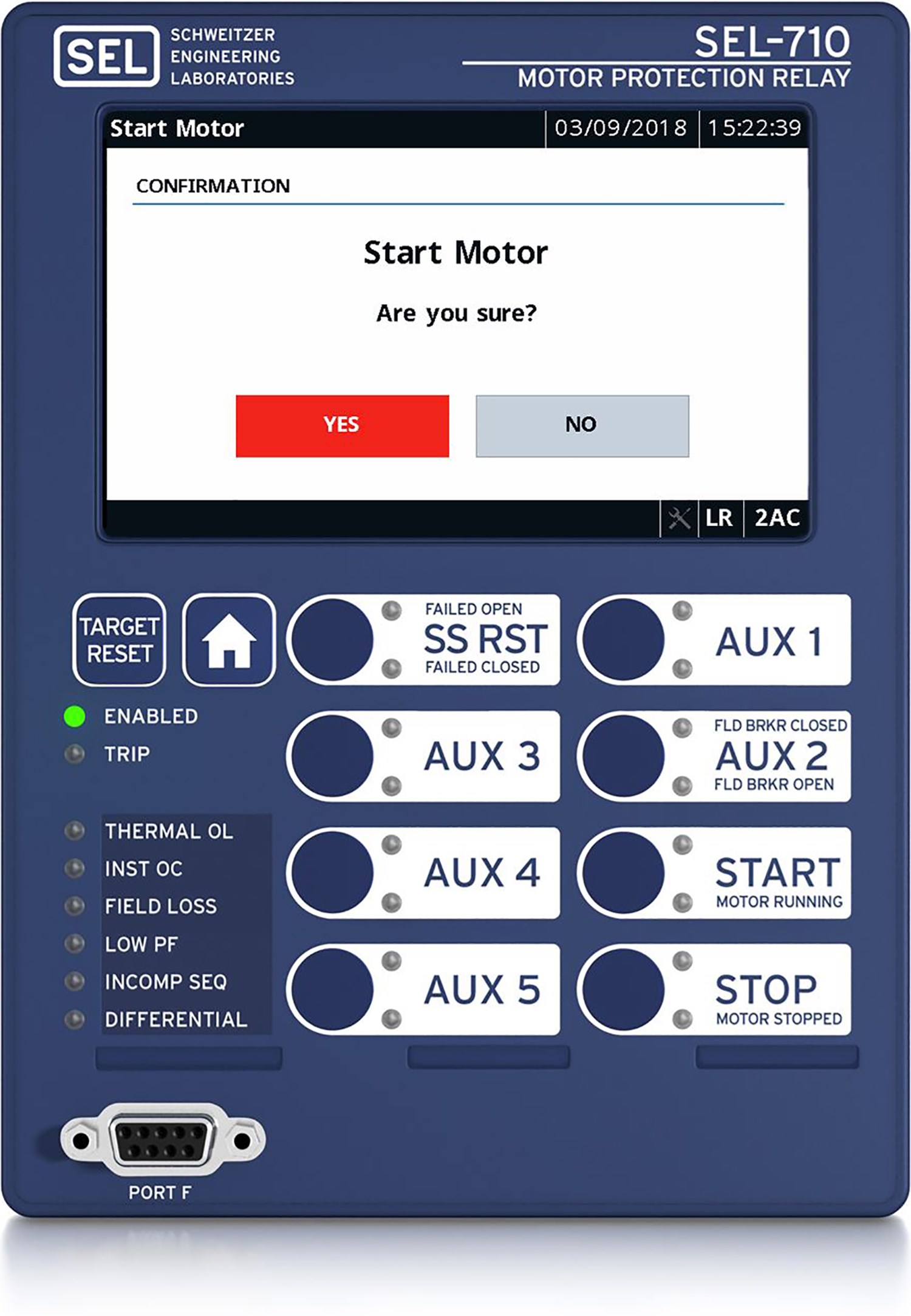
-
-
- 1
Fundamental Metering
View the real, reactive, and apparent power of each phase in your system, and monitor the power factor information to determine if the phase current leads or lags the phase voltage.
1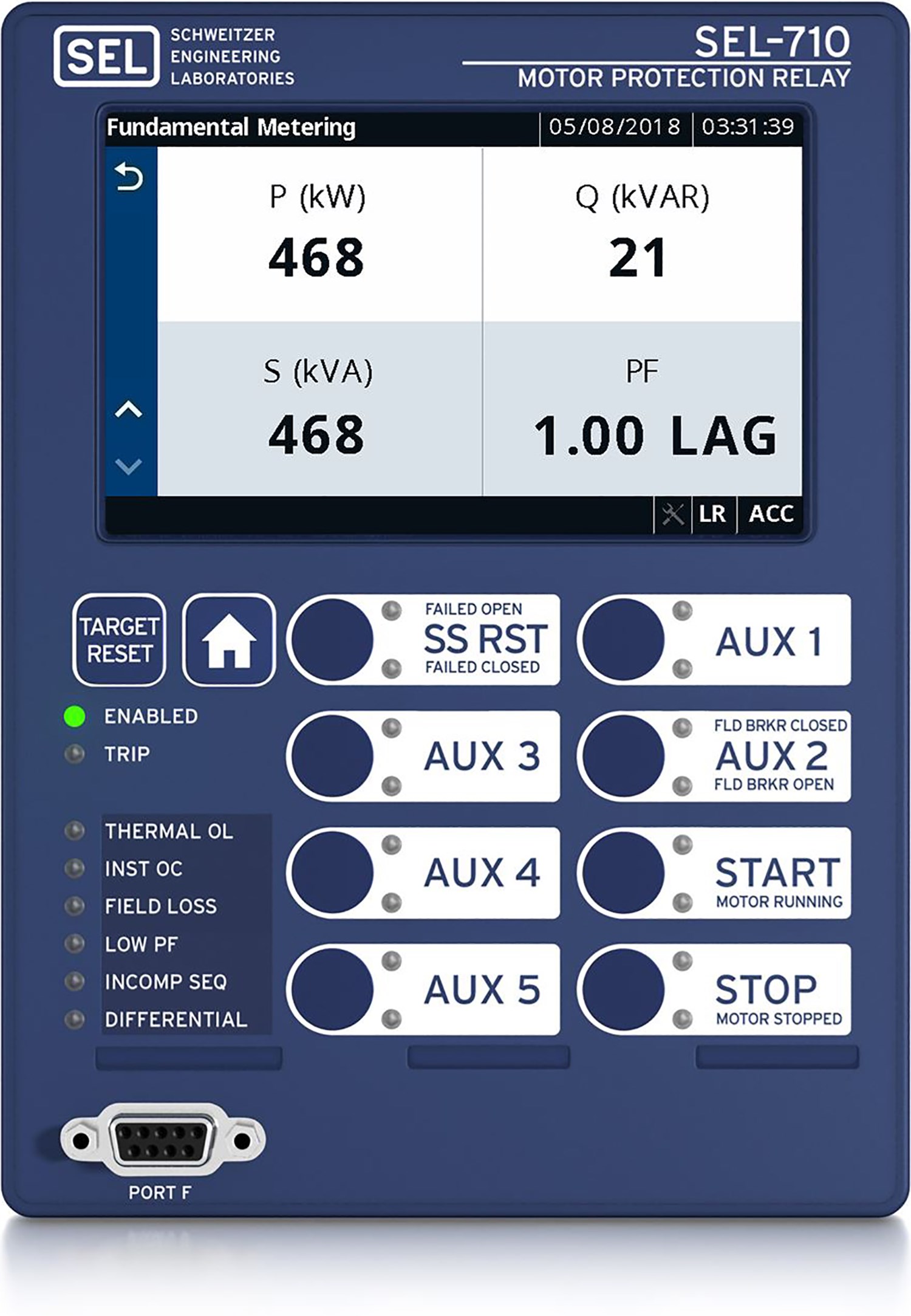
-
-
- 1
Meter Phasors
View a graphical and textual representation of the real-time voltages and currents in a power system during balanced and unbalanced conditions. By analyzing the phasors, you can determine power system conditions.
1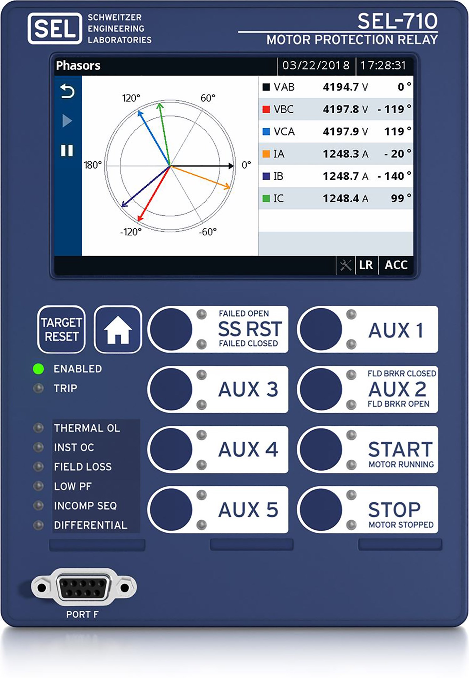
-
-
- 1
Vibration Monitoring
View critical motor vibration data to identify potential defects and respond before motor failures occur. The display provides intuitive graphical feedback to enable timely operator response.
1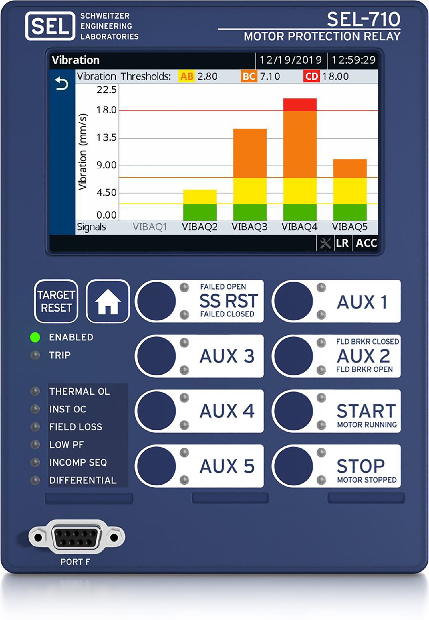
-
-
- 1
Sequential Events Recorder
Easily review the time-stamped Sequential Events Recorder (SER) data, including whether or not the Relay Word bit asserted or deasserted, during root cause analysis of an event.
1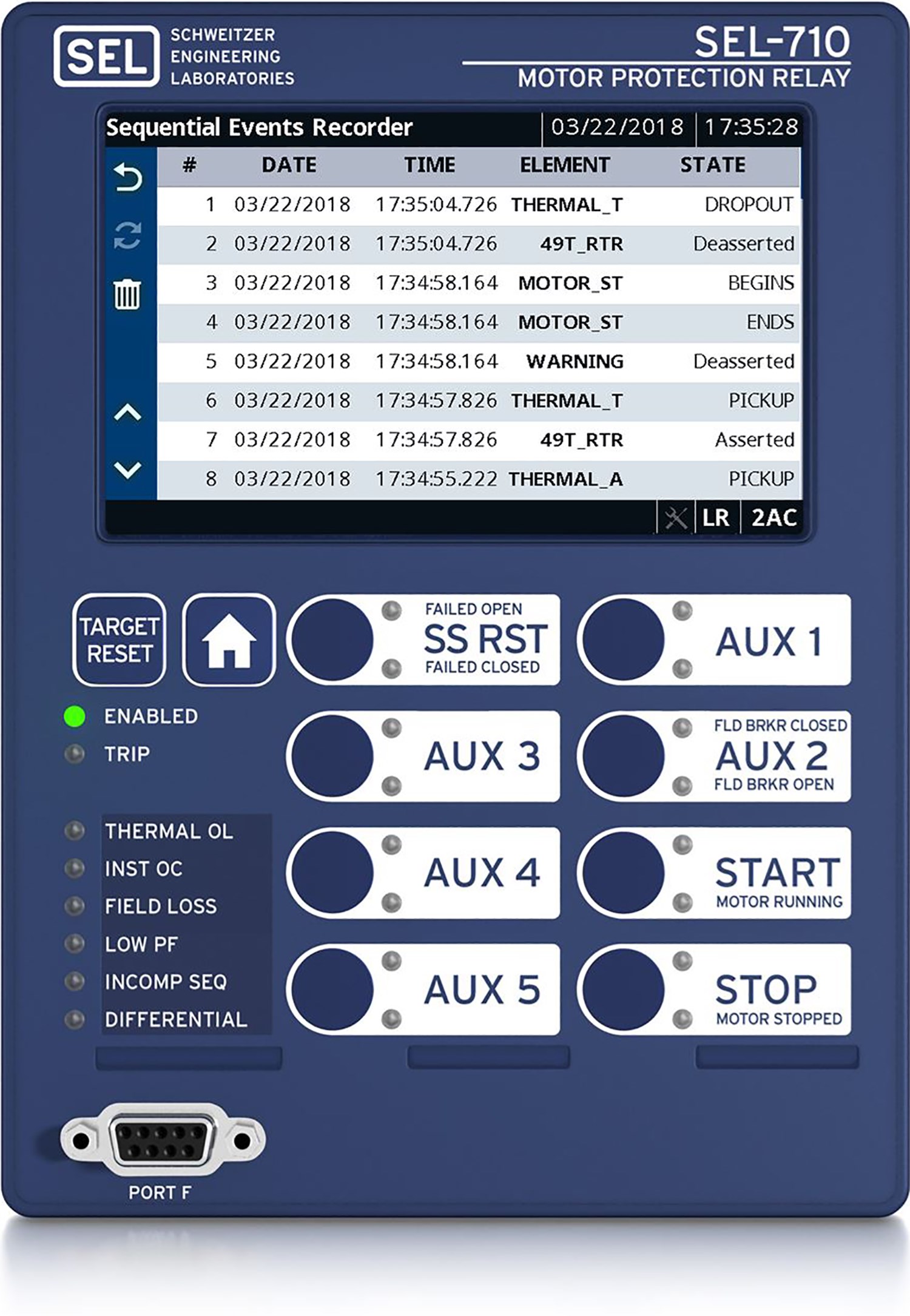
-
Details
Advanced Protection
The SEL-710-5 provides advanced protection for induction and synchronous motors. Protection includes thermal overload, overcurrent, undercurrent, current unbalance, current differential, phase loss, ground fault, loss-of-field, over- or underfrequency, and much more.
Optimized Start Times
The SEL-710-5 calculates percent of thermal capacity used in the motor to determine maximum safe start times with full motor protection. Accurate tracking of the motor thermal capacity also minimizes the time needed between starts.
Easy Communications
Quickly integrate the SEL-710-5 into serial- or Ethernet-based communications with IEC 61850 Edition 2, EtherNet/IP, IEEE 1588 PTP, IEC 60870-5-103, PRP, Mirrored Bits communications, DNP3 serial, DNP3 LAN/WAN, and other protocols.
Web Server Access
The built-in web server enables secure, remote access to the relay with password protection. You can download status reports or view metering and relay information remotely. This helps minimize trips to the relay location, saving time and money.
Accelerated Firmware Downloads
Simplify maintenance by downloading relay firmware via the Ethernet port. This also enables you to access and update all of your network relays simultaneously.
IEC 61850 Edition 2 Communications Protocol
Combine IEC 61850 Edition 2, an Ethernet network, and the SEL-710-5 for the fastest overall performance for substation automation and control. You can improve security using the password authentication and session time-out features, transfer event files in COMTRADE and CEV formats, and transfer CID files, settings, and reports. acSELerator Architect SEL-5032 Software streamlines the configuration of IEC 61850 in the SEL-710-5.
IEC 61850 Test Mode
Use the IEC 61850 Test Mode to test system components in energized substations without fear of operating control output contacts.
Simple Network Time Protocol (SNTP)
Simplify wiring and installation by receiving a time signal over existing Ethernet networks. SNTP makes a good backup to more accurate IRIG-B time synchronization. The 1 ms accuracy is ideal for basic time synchronization throughout a substation.
Optional Touchscreen Display
The easy-to-use touchscreen interface provides a one-line mimic display for bay control and monitoring. You can view metered quantities, phasor diagrams, relay settings, event summaries, target statuses, Sequential Events Recorder (SER) data, and more. Extensive testing shows that the robust capacitive touchscreen display meets or exceeds industry standards as well as SEL quality and reliability requirements.
Incipient Fault Detection
Identify potential cable failures to extend asset life and minimize unexpected downtime. The SEL-710-5 checks for self-extinguishing half-cycle faults, providing an indication of imminent cable failures.
Asset Monitoring
Track the operating characteristics of your motor and accompanying devices with the predictive maintenance capability. You can reduce production losses from unexpected equipment failures and lower maintenance costs by switching to condition-based maintenance schedules.
Expanded SELogic Control Equations
Use math and logic combinations of analog and digital values for customized applications. You can adapt system control based on prefault conditions and scale analog values and latch momentary inputs for SCADA retrieval.
Metering and Reporting
View SER and 180-cycle oscillographic event reports in COMTRADE and CEV formats for rapid commissioning, testing, and post-fault diagnostics. Ethernet FTP or IEC 61850 MMS allows you to easily retrieve COMTRADE files.
AccuTrack Thermal Model
Apply the SEL-710-5 to dynamically calculate motor slip and precisely track the rotor thermal capacity used. The AccuTrack Thermal Model uses this information to reduce the time between starts and give the motor more time to reach its rated speed before tripping.
Motor Thermal Overload Protection
The SEL-710-5 provides locked-rotor, running overload, and negative-sequence current unbalance protection. It uses the AccuTrack Thermal Model to accurately track the heating effects of load current and current unbalance during the motor’s operating conditions (starting and running).
Arc-Flash Detection
AFD-based protection is fast, responding in a few milliseconds with high-speed, high-current interrupting output contacts. This fast response, supervised by phase overcurrent elements, provides high-speed and secure arc-flash protection that improves personnel safety and reduces equipment damage. Arc-flash mitigation options in the SEL-710-5 offer either four or eight AFD inputs capable of reading both point and loop sensors.
Rugged Design
Trust the industry’s widest ambient operating temperature range, –40° to +85°C (–40° to +185°F). The SEL-710-5 withstands vibration, electrical surges, fast transients, and extreme temperatures, meeting stringent industry standards. A conformal-coating option for the printed circuit boards provides an additional barrier to airborne contaminants, such as hydrogen sulfide, chlorine, salt, and moisture. In addition, the SEL-710-5 is ATEX-certified and UL Class I, Division 2-certified for use in hazardous and potentially explosive environments.

- Synchronous and induction motor protection
- Electromechanical relay retrofit

- Medium-voltage motor protection
- 5-inch color touchscreen display with 8 pushbuttons
- High-speed AFD

- Synchronous and induction motor protection
- 5-inch color touchscreen display with 8 pushbuttons
- Advanced communications protocols, including IEC 61850 and DNP3
Minimum Software Version
| Product | Revision | Z Number | acSELerator QuickSet Version | SEL Grid Configurator Version |
|---|---|---|---|---|
| SEL-710-5 | R102-V0 | 002 | 6.6.0.0 | |
Please contact Application Engineer for firmware related to your hardware platform. The current revision does not apply to all hardware. | ||||
Latest Firmware Versions
There are no firmware versions available for this product.
| Product | Revision | Firmware ID | Date Available | Serial Number |
|---|---|---|---|---|
| SEL-710-5 | R303-V1 | SEL-710-5-R303-V1-Z006003-D20250214 | 3/27/25 | ~3250860001 |
| SEL-710-5 | R302-V2 | SEL-710-5-R302-V2-Z005003-D20240826 | 10/16/24 | ~3242900001 |
| SEL-710-5 | R300-V6 | SEL-710-5-R300-V6-Z004003-D20220826 | 10/27/22 | ~3223000001 |
| SEL-710-5 | R201-V6 | SEL-710-5-R201-V6-Z003002-D20250214 | 3/27/25 | ~3250860001 |
The Firmware IDs for older versions of the firmware can typically be found in Appendix A of the instruction manual.
Minimum Software Version
| Product | Revision | Z Number | acSELerator QuickSet Version | SEL Grid Configurator Version |
|---|---|---|---|---|
| SEL-710-5 | R102-V0 | 002 | 6.6.0.0 | |
Please contact Application Engineer for firmware related to your hardware platform. The current revision does not apply to all hardware. | ||||
Instruction Manuals
Sales Resource Central access is required to view the content in this tab.
Sales Resource Central710-5 - Software Tab
Configuration
acSELerator QuickSet SEL-5030 Software
QuickSet is a tool for engineers and technicians to quickly and easily configure, commission, and manage power system devices. QuickSet includes a Graphical Logic Editor and a device template tool to reduce configuration time and streamline deployment.
Learn more and download on the QuickSet software page.
acSELerator Architect SEL-5032 Software
Architect allows users to configure and document IEC 61850 systems that include GOOSE, Sampled Values (SV), or Manufacturing Message Specification (MMS) communications. Architect automatically compares SCL files with IEC 61850 requirements to ensure standard compliance.
Learn more and download on the Architect software page.
Automated Data Collection
SEL Data Management and Automation (DMA) Application Suite
Available on the Blueframe platform, DMA applications automatically collect, store, and manage device-specific information like oscillography, Sequence of Events (SOE) data, device settings, and property information. They also provide automated password rotation and streamlined device audits.
Learn more on the DMA software page.
Visualization and Analysis
SEL-5601-2 Synchrowave Event Software
Synchrowave Event helps engineers diagnose a protective relay’s behavior during a power system fault. It is a powerful and easy-to-use solution for displaying and analyzing SEL relay event reports and COMTRADE files.
Learn more and download on the Synchrowave Event software page.


