
SEL-7200
Configure-to-Order (CTO) Panels and Retrofit Plates
Increased quality, faster lead times, and reduced total cost of ownership.
The SEL-7200 CTO family of panels and retrofit plates provides predesigned, advanced solutions for protection, control, automation, communications, and cybersecurity in different substation applications.
- A consistent, methodical design and manufacturing approach offers higher quality, reliability, and performance than traditional custom panels.
- Predesigned and validated settings for application modules speed up deployment while guaranteeing functionality.
- Achieve up to a 40 percent savings in total cost of ownership versus a comparable custom panel.
SEL CTO panels embody SEL best-known engineering methods and field-tested expertise in mechanical design, cable management, protection, precise time, automation, and communications.
Components and functionalities associated with a specific substation application (e.g., feeder protection and control) are co-located and designed as an application module. Application modules support common protection and automation practices while universal wiring to terminal blocks allows customization to adapt to any common primary equipment configuration and operation practice.
If you would like to talk to an SEL representative or configure an SEL panel, click on the “Contact Us” button below and fill out the contact form. A representative from our engineering services team will follow up within the next business day.
SEL-7201 Feeder Protection Panel—These panels provide advanced protection and control for up to four feeders. They offer protection functions, such as overcurrent, voltage, frequency, and breaker failure elements, as well as control functions, such as reclosing, sync-check, and hot-line tagging.
SEL-7202 Line Protection Panel—These panels provide the most advanced and fastest protection and control for two-terminal, two-breaker transmission lines using phasors and time-domain technology.
SEL-7203 Distribution Transformer Protection Panel—SEL-7203 panels provide advanced protection and control for distribution transformers with a single high-/low-side transformer zone boundary.
SEL-7206 Distribution Bus Differential Protection Panel—SEL-7206 panels provide optimized low-impedance bus differential protection for distribution buses with up to five feeders.
SEL-7207 Automation and Communications Panel—These panels provide high-accuracy time synchronization; centralized engineering access with user-based authentication and authorization; data collection for SCADA; and inherently cybersecure, reliable, and high-performance Ethernet communications using SEL software-defined networking (SDN) technology.
SEL-7210 Retrofit Protection Plates—Retrofit and modernize existing panels or switchgear to get all the benefits of CTO solutions. Fifteen-foot pigtails allow connection to your existing terminal blocks.
Related Materials


Human error is often referenced as the main cause for events that occur in the power system. With standardized applications, co-located components, adequate space, and improved labeling, SEL CTO panels help increase safety for personnel and reduce the possibility for error.
By organizing components and functionalities into application modules, SEL leverages world-class manufacturing principles to provide a more robust, consistent, and repeatable product.
All components associated with an application module are physically co-located, reducing the possibility for mistakes while simplifying the installation, commissioning and future module additions or upgrades.
Connections are positioned within easy reach for technicians and every wire is labeled at both ends to make connections obvious and to speed up troubleshooting.


Application modules are mechanically assembled, wired, and tested in the production line for faster production and delivery.
All wires are cut, stripped, and crimped on state-of-the-art automated equipment, eliminating waste, guaranteeing repeatability, and ensuring the quality of each crimp.
Features
- Front
- Back
- SEL-7201 Feeder Protection Panel
- SEL-7202 Line Protection Panel
- SEL-7203 Distribution Transformer Protection Panel
- SEL-7206 Distribution Bus Differential Protection Panel
- SEL-7207 Automation and Communications Panel
-
- 1
Open-back rack structure; 92" tall × 28" wide × 28" deep
- 2
EIA-compliant 19" rack with universal hole spacing and 48 rack units of equipment space
- 3
Load capacity of 1,700+ pounds and multiple anchoring options
- 4
ANSI 61 gray textured finish; powder coat paint
- 5
Removable eye bolts and sockets for easy maneuvering during site installation
- 6
Convenience ac outlet and cable pass-through
- 7
Manufactured with no sharp edges that can damage wiring or people
- 8
Customized lamicoid engraved nameplates for all equipment
- 9
Electrical bonding and grounding per UL 508A
123456789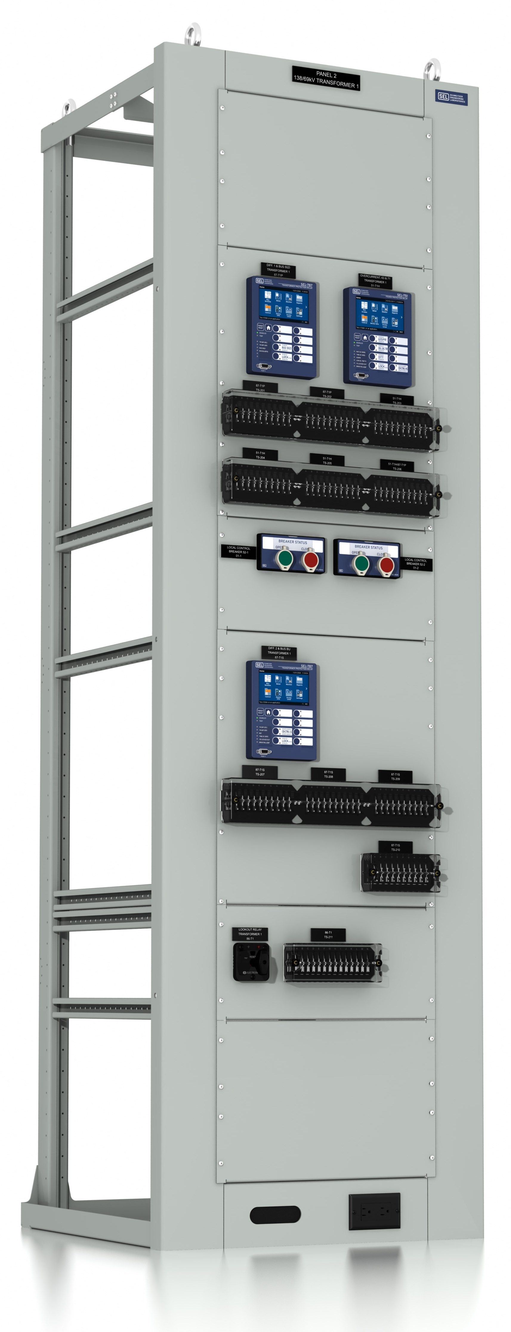
-
-
- 1
Workmanship per IPC-A-620C Class 3
- 2
Co-located components per application allow better/safer human interaction
- 3
Secondary voltage input protection/isolation using MCBs
- 4
Secondary current input isolation using short-circuiting terminal blocks with bolt-type connections
- 5
Terminal blocks with bolt connection and captive cap for all other signals, allowing the use of ring- or fork-type terminals
- 6
Dead-front terminal blocks to avoid unintended personnel contact with live parts
- 7
45-degree angled terminal blocks for easier visibility and accessibility
- 8
600 V SIS UL-labeled wire used for all connections; 12 AWG for currents and ground and 14 AWG for all other signals
- 9
Dedicated test switches to isolate the protective relays for commissioning and routine testing
- 10
Ample field cable access from top or bottom and physical separation for field and internal wiring
- 11
Wiring labels with origin and destination information
- 12
Electrical bonding and grounding per UL 508A
123456789101112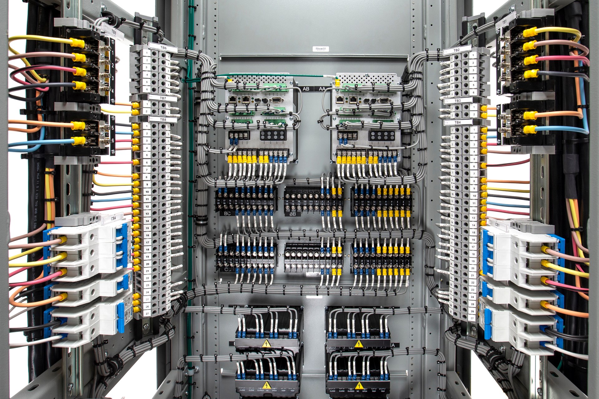
-
-
- 1
Advanced protection and control for two feeders using SEL-751 Feeder Protection Module
- 2
Independent breaker control and indication using SEL-9510 Control Switch Module
- 3
Customized lamicoid engraved nameplates for all equipment
- 4
Convenience ac outlet and cable pass-through
- 5
Dedicated test switches to isolate the protective relays for commissioning and routine testing
- 6
Space available for future automation, communications, or customer-specific equipment
123456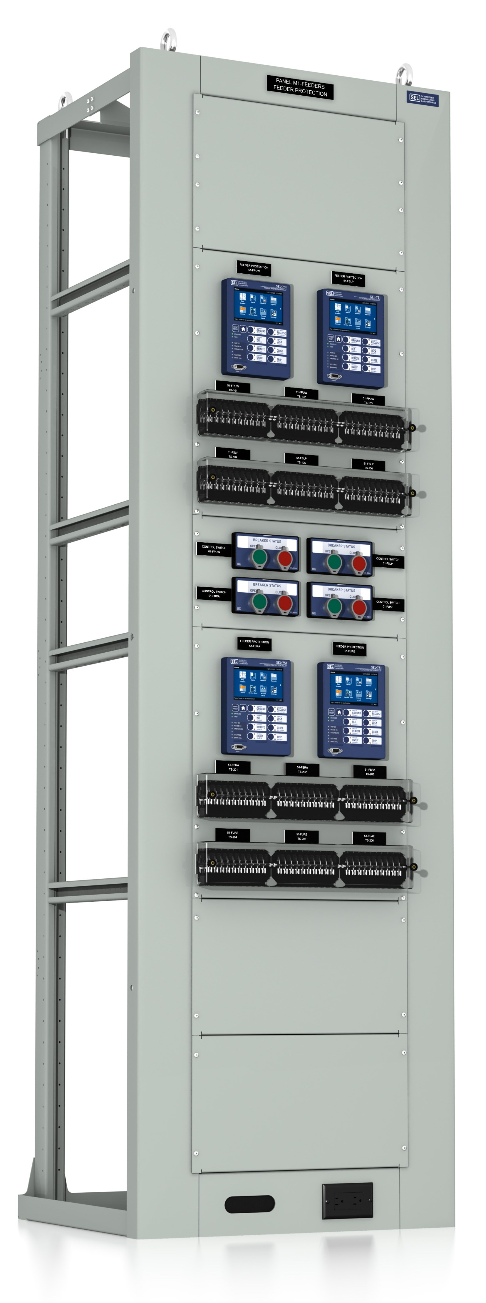
-
-
- 1
Line current differential, distance, and pilot protection plus breaker failure protection and reclosing for two breakers using the SEL-411L Line Current Differential Module
- 2
Ultra-high-speed line protection using time-domain technology of traveling waves and incremental quantities with the SEL-T401L Ultra-High-Speed Line Protection Module
- 3
Reliable dc power for protection and control equipment in the panel using the SEL-RPM Redundant Power Module
- 4
Customized lamicoid engraved nameplates for all equipment
- 5
Convenience ac outlet and cable pass-through
- 6
Dedicated test switches to isolate the protective relays for commissioning and routine testing
- 7
Space available for future automation and communications modules or other equipment
1234567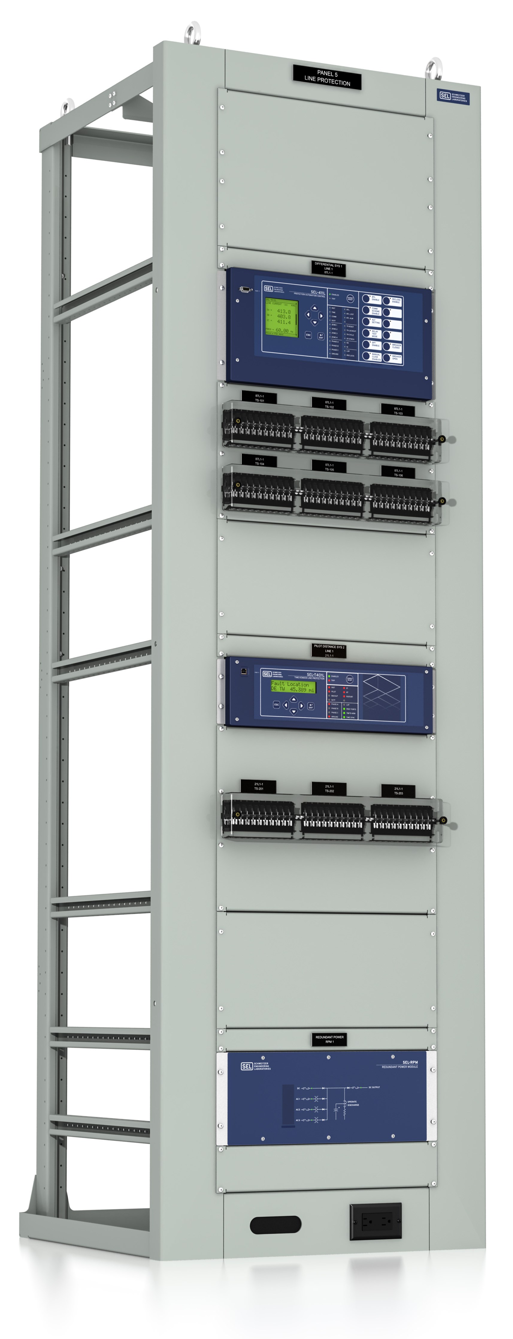
-
-
- 1
Differential protection and overcurrent backup protection using SEL-787/SEL-751 Transformer Protection Module
- 2
Redundant differential protection using SEL-787 Redundant Transformer Protection Module
- 3
Independent breaker control and indication for high- and low-side switching devices using SEL-9510 Control Switch Module
- 4
Transformer (86T) Lockout Relay Module
- 5
Customized lamicoid engraved nameplates for all equipment
- 6
Convenience ac outlet and cable pass-through
- 7
Dedicated test switches to isolate the protective relays for commissioning and routine testing
- 8
Space available for future automation, communications, or customer-specific equipment
12345678 -
-
- 1
Subcycle low-impedance bus differential protection for five feeders, tie breaker, and source as well as overcurrent backup protection using SEL-487B Distribution Bus Protection Module
- 2
Bus (86B) Lockout Relay Module
- 3
Customized lamicoid engraved nameplates for all equipment
- 4
Convenience ac outlet and cable pass-through
- 5
Dedicated test switches to isolate the protective relays for commissioning and routine testing
- 6
Space available for second SEL-487B Distribution Bus Protection Module
- 7
Space available for future automation, communications, or customer-specific equipment
1234567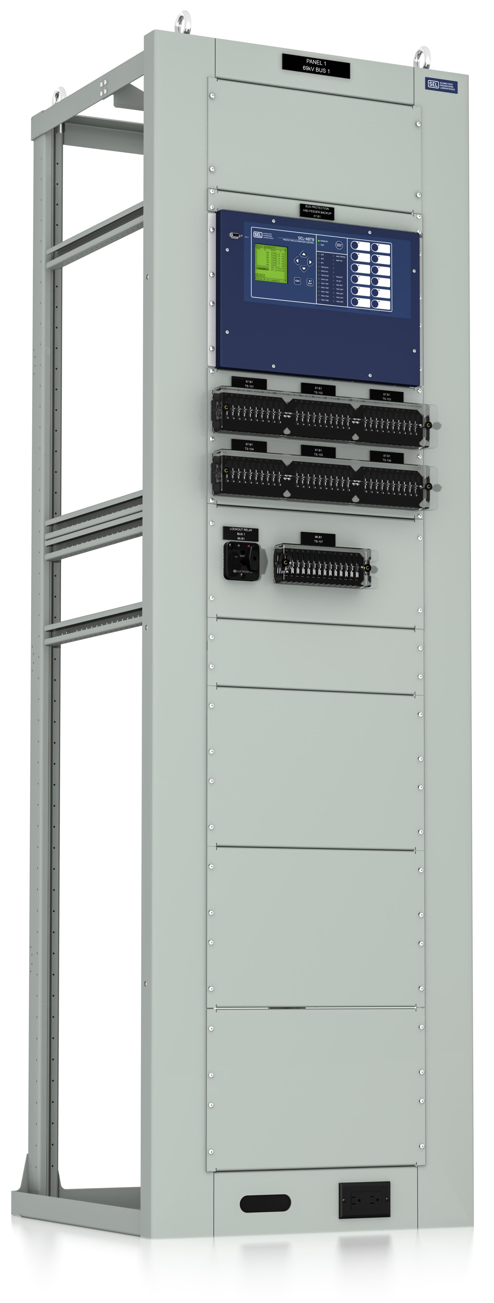
-
-
- 1
Precise time synchronization, firewall, routing, VPN management, user-based authentication and authorization, IED password management, Syslog, and high-performance operational technology (OT) SDN using SEL Time, Cyber, and Communications Module
- 2
Data concentration, system database, SCADA communications, engineering access, and substation control using SEL System Automation Module
- 3
Serial port expansion using SEL Port Server Module
- 4
Ethernet port expansion using SEL SDN Ethernet Switch Module
- 5
Convenience ac outlet and cable pass-through
- 6
Space available for future automation, communications, or customer-specific equipment
123456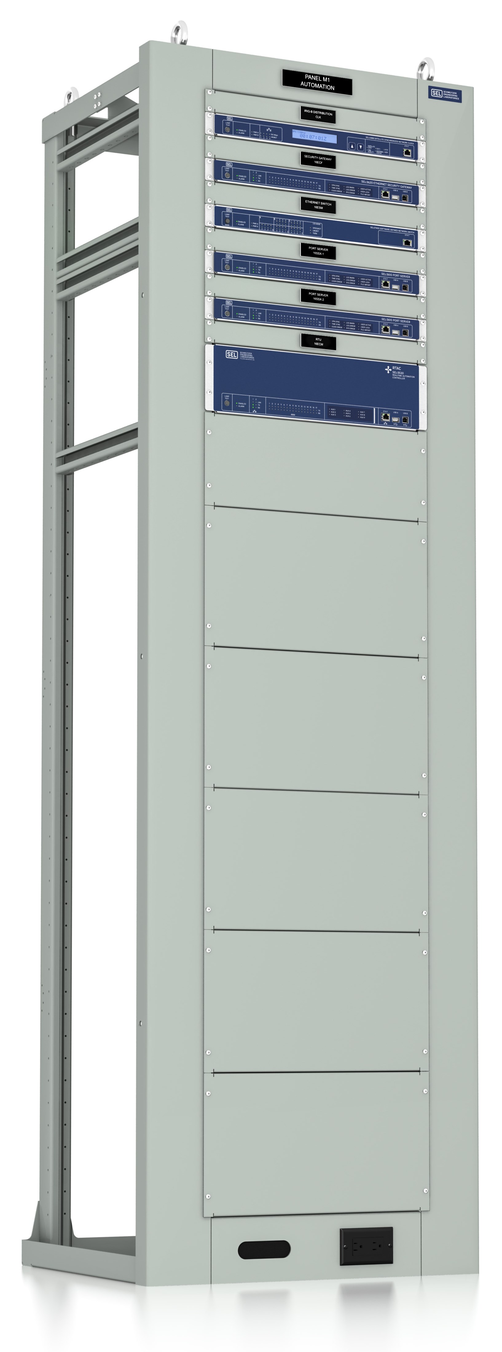
-
Details
SEL CTO panels embody SEL best-known engineering methods and field-tested expertise in mechanical design, cable management, protection, precise time, automation, communications, and metering.
Application modules support common protection and automation practices while universal wiring to terminal blocks allows customization flexibility to adapt to any common primary equipment configuration and operation practice.
The SEL Difference
SEL uses the same world-class manufacturing principles for our panels that we use for all our industry-leading products. This allows us to design, manufacture, test, and deliver top-quality and comprehensive panel systems.
Complete vertical integration and standardized application designs help us maintain competitive prices and high quality while still meeting the highest functionality requirements.
Design Principles
SEL CTO panels provide the following:
- Fully redundant protection and breaker failure protection at all voltage levels.
- Preconfiguration for cybersecurity framework integration.
- Advanced SEL technology, such as arc-flash protection, zone-interlocked bus protection logic, and negative-sequence overcurrent protection, that is ready to deploy.
- Simple integration to SCADA and HMI.
- Continuous monitoring to reduce the possibility of hidden failures and facilitate extended testing intervals.
- An industrial design for improved human performance.
Design Validation That Guarantees Expected Performance
We build a prototype and test each application module design to ensure it meets functional specifications. This process allows our manufacturing facility to properly document processes and test manufacturing equipment for production.
Drawing Package
SEL CTO panels come with comprehensive information using best practices for documenting protection and control circuitry. With standardization, the level of error-free detail is unmatched compared to what is practical with custom panels. SEL drawing packages are personalized to your substation project and nomenclature and include:
- Application-specific circuit information.
- One-line diagram customized with your primary equipment information.
- AC schematics diagrams documenting relay sensing circuits, protection functions, and space to incorporate customer primary equipment information.
- DC schematic diagrams with panel control circuits and space to include external connection points from marshalling cabinets and primary equipment.
- Comprehensive logic diagrams documenting logic settings for the application, including local/remote control and indication, target LEDs, fault protection, alarms, event report triggers, open, close, reclose, and trip.
- Panel layout drawing containing device locations, dimensions, and anchoring details.
- Wiring diagram with wiring label nomenclature.
- Nameplate drawing that includes all labels created and installed in the panel.
Quality
We engineer, manufacture, and test our panels to ensure adequate operation before delivery. When a panel arrives at your site, it is already verified as fully functional.
Warranty and Support
SEL panels are supported by an unmatched ten-year warranty and the industry’s best customer service.
The Firmware IDs for older versions of the firmware can typically be found in Appendix A of the instruction manual.