
SEL-7251
Electromechanical Direct-Replacement Assemblies
Streamline retrofit projects by replacing electromechanical relays with SEL direct-replacement assemblies. These complete, preassembled retrofit kits combine a field-proven SEL digital relay with mounting plates, interposing terminal blocks, test switches, and other hardware that closely match the function, form factor, and terminal blocks of specific legacy relays.
Simplify Installation and Configuration—Install direct-replacement assemblies in only a few hours. Assemblies are designed to replace sets of three electromechanical relays on the same panel; just a few simple cuts are required to remove the dividers between the old relays. Terminal block arrangements and wiring designations closely match legacy products, and SEL provides wiring labels with the retrofit kits to complete the upgrade process.
Modernize With Advanced Technology—SEL solutions offer the fastest, most reliable protection available. They also improve systemwide visibility and control through cybersecure remote engineering access, automated event collection, and precise fault location, among other benefits.
Minimize Engineering Work—Eliminate time-intensive and costly engineering tasks, such as revising drawings and diagrams. All assembly kits include conversion drawings, so modification of the existing documentation for your system is not required for installation.
Target Specific Assets for Upgrades—Extend the life of your existing switchgear while maximizing uptime with direct-replacement assemblies. Avoid the need for extended outages and capital requests to replace switchgear by upgrading your legacy equipment piece by piece and modernizing in economical stages.
Partner With SEL on a Turnkey Solution—SEL offers services that include system design, settings conversion, installation, and commissioning—everything needed for a complete turnkey retrofit solution. We also create custom assembly designs to meet specific protection, communications, and mounting requirements.
Receive Comprehensive Support—All SEL-manufactured products and workmanship within panels and enclosures are backed by a worldwide, ten-year warranty. Diagnostic services, repairs, and local technical support are available for the lifetime of every SEL-manufactured device—at no extra cost. Third-party devices carry a transferred manufacturer warranty.

Purpose-Built Replacements
Direct-replacement assemblies are available to replace the electromechanical relay models listed below.
Features
- GE BDD Differential Relay to SEL-787
- GE IAC or IFC Relay to SEL-751
- GE IAC or IFC Relay to SEL-751 (Vertical Alignment)
- GE IAC or IFC Relay to SEL-851
- GE IAC or IFC Relay With Westinghouse RC Automatic Reclosing Relay to SEL-751
- GE PVD High-Impedance Bus Differential Relay
- Westinghouse CO Relay FT-21 Chassis or Basler BE1-50/51B Relay to SEL-751
- Westinghouse CO Relay FT-11 Chassis or Basler BE1-50/51B Relay to SEL-851
- Westinghouse KAB Relay to SEL-787Z and SEL-HZM
-
- 1
SEL-787
- 2
Relay power, CT, and control terminal blocks
- 3
Relay mounting plate
- 4
SEL-787
- 5
Two 14-pole test switches with clear covers
- 6
Configurable label nameplate for test switches
123456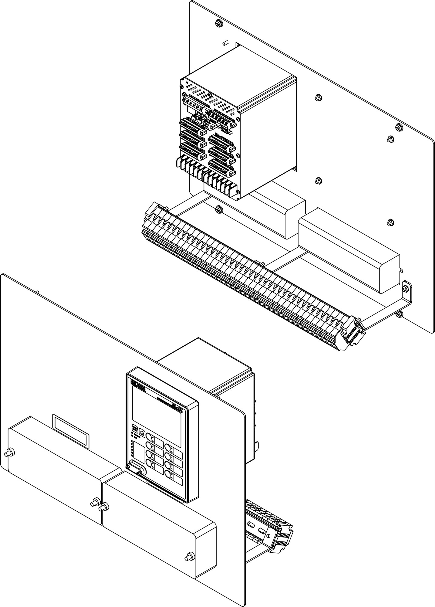
-
-
- 1
Neutral relay plate (if applicable)
- 2
Neutral relay CT and control terminal blocks (if applicable)
- 3
Relay power and PT terminal block
- 4
SEL-751
- 5
CT and control terminal blocks
- 6
SEL-751
- 7
Configurable nameplate
- 8
Relay mounting plate
- 9
14-pole test switch with clear cover
- 10
Neutral terminal block plate (if applicable)
12345678910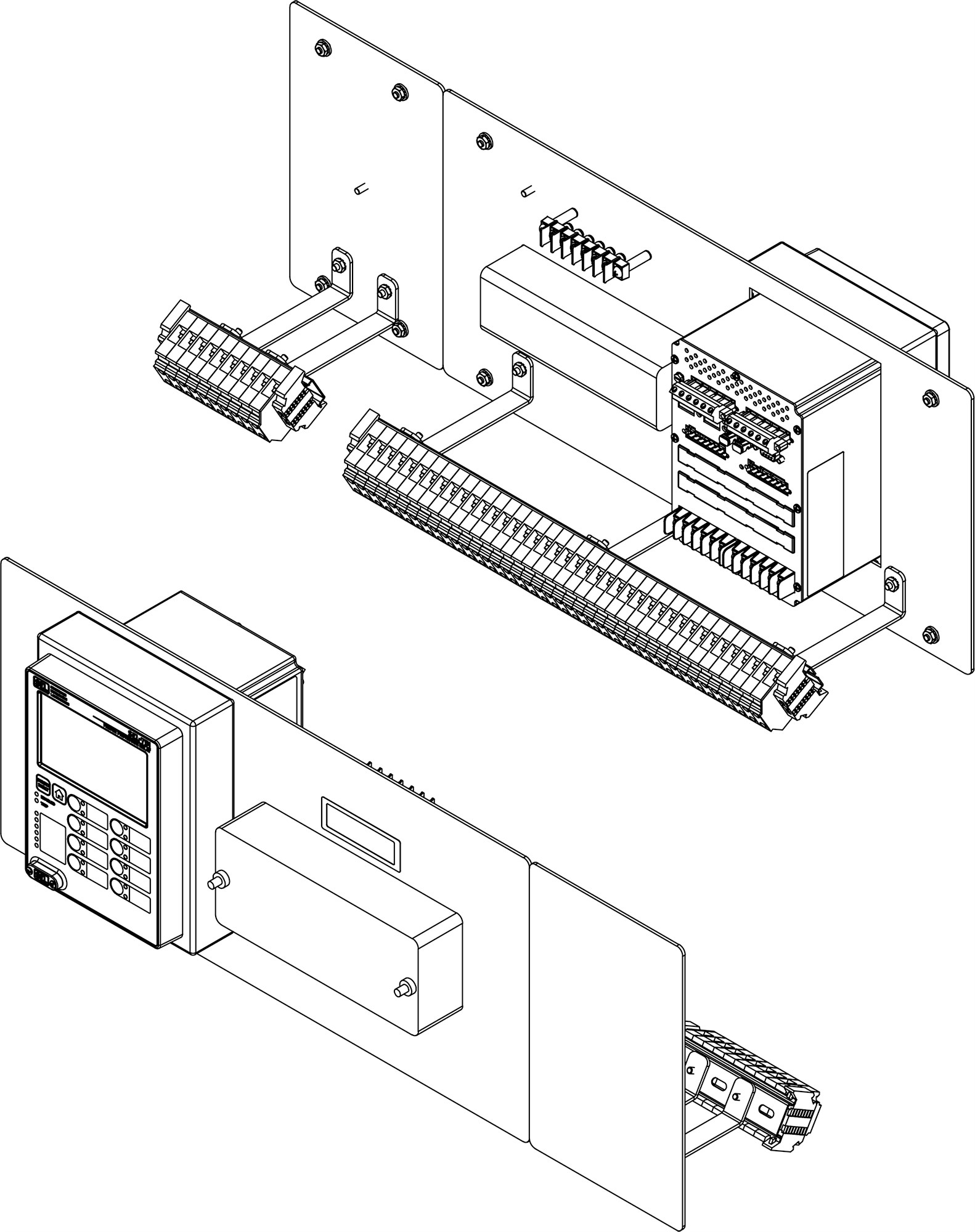
-
-
- 1
SEL-751
- 2
Relay mounting plate
- 3
Two 10-pole test switches with clear covers
- 4
Two configurable nameplates
- 5
Relay CT and control terminal blocks
- 6
Neutral relay plate (if applicable)
- 7
Neutral relay CT and control terminal blocks (if applicable)
1234567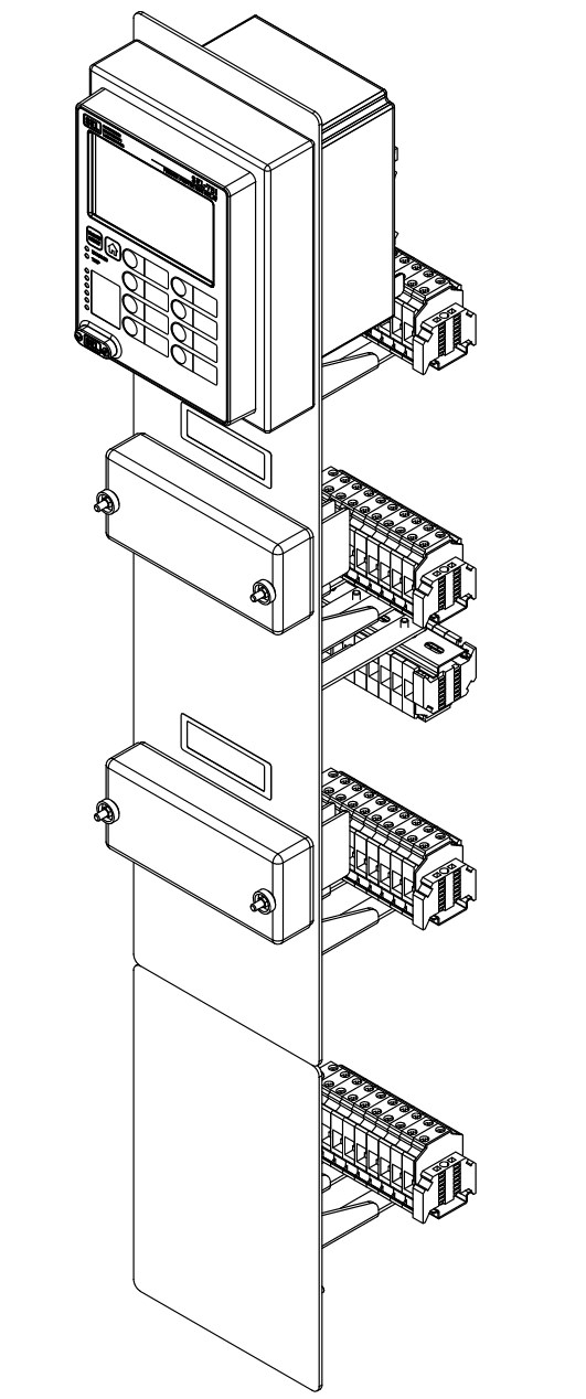
-
-
- 1
Neutral relay plate (if applicable)
- 2
Relay power and PT terminal block
- 3
SEL-851
- 4
Neutral relay CT and control terminal blocks (if applicable)
- 5
CT and control terminal blocks
- 6
SEL-851
- 7
Relay mounting plate
- 8
Configurable nameplate
- 9
14-pole test switch with clear cover
- 10
Neutral terminal block plate (if applicable)
12345678910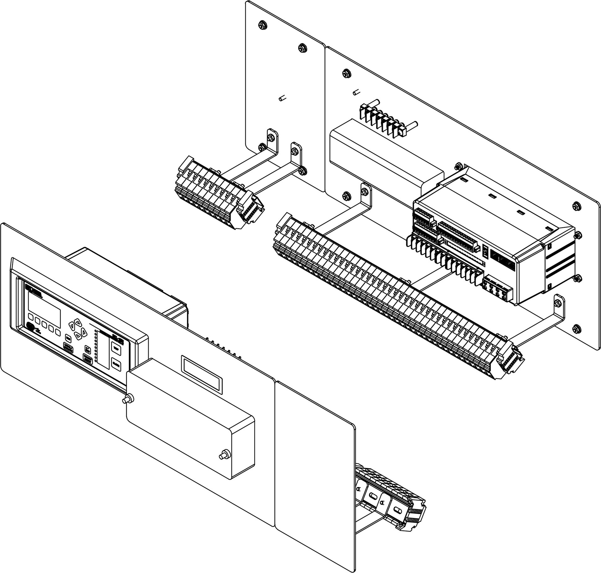
-
-
- 1
SEL-751
- 2
Relay mounting plate
- 3
Configurable nameplate
- 4
14-pole test switch with clear cover
- 5
Neutral terminal block plate (if applicable)
- 6
Automatic reclosing relay terminal block plate
- 7
Automatic reclosing relay CT and control terminal blocks
- 8
Automatic reclosing relay CT and control terminal blocks
12345678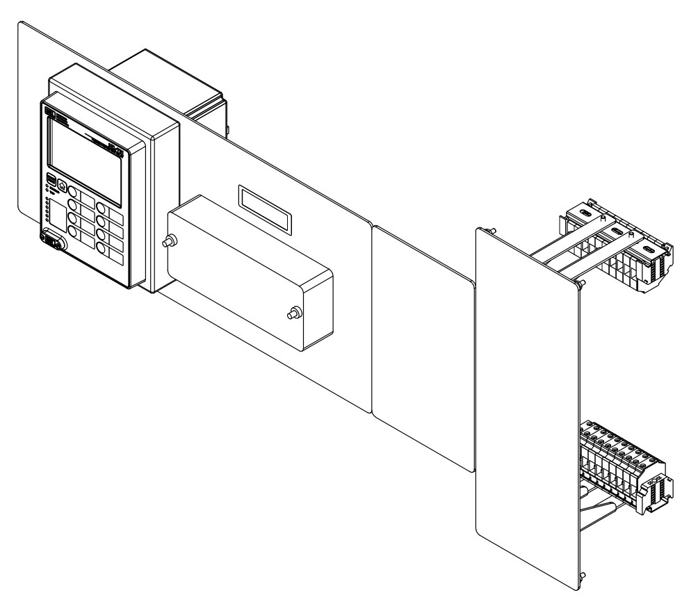
-
-
- 1
SEL-787Z
- 2
SEL-HZM
- 3
Relay power, CT, and control terminal blocks
- 4
SEL-HZM
- 5
Relay mounting plate
- 6
Configurable label nameplate for test switches
- 7
Two 14-pole test switches with clear covers
- 8
SEL-787Z
12345678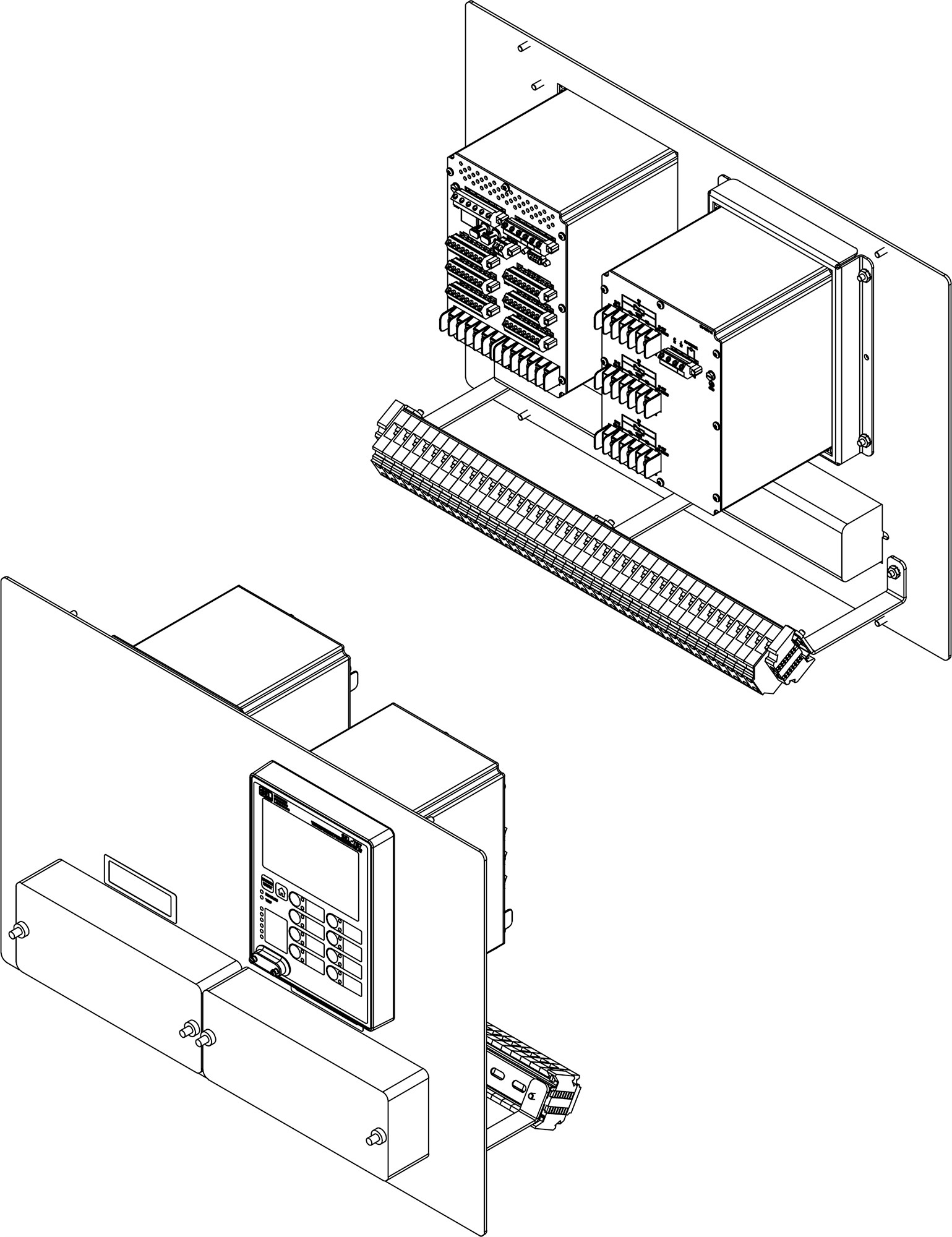
-
-
- 1
Neutral relay plate (if applicable)
- 2
Relay power and PT terminal block
- 3
SEL-751
- 4
Neutral relay CT and control terminal blocks (if applicable)
- 5
CT and control terminal blocks
- 6
SEL-751
- 7
Relay mounting plate
- 8
Configurable label test switch nameplate
- 9
14-pole test switch with clear cover
- 10
Neutral terminal block plate (if applicable)
12345678910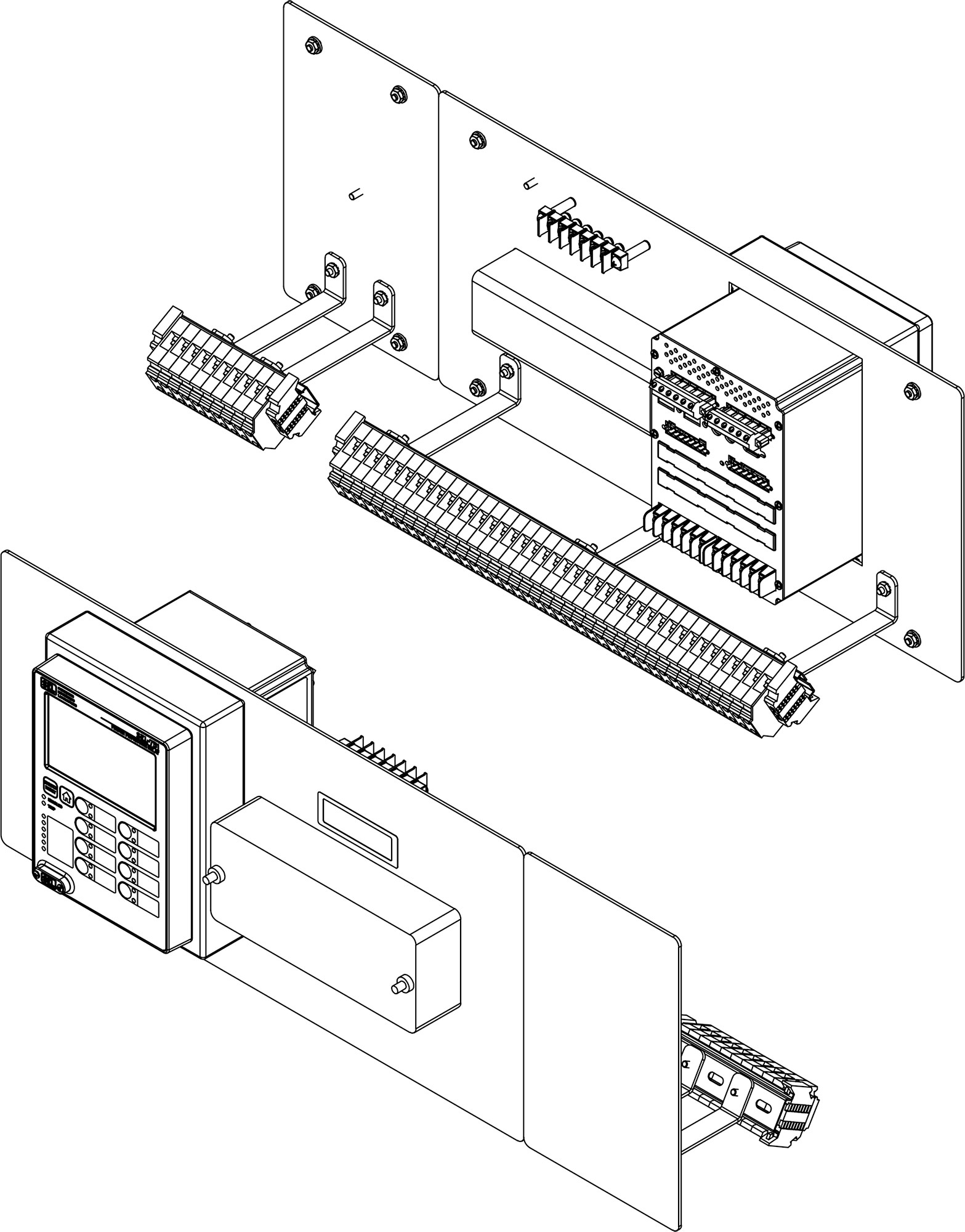
-
-
- 1
Neutral relay plate (if applicable)
- 2
Relay power and PT terminal block
- 3
SEL-851
- 4
Neutral relay CT and control terminal blocks (if applicable)
- 5
CT and control terminal blocks
- 6
SEL-851
- 7
Relay mounting plate
- 8
Configurable nameplate
- 9
Neutral terminal block plate (if applicable)
123456789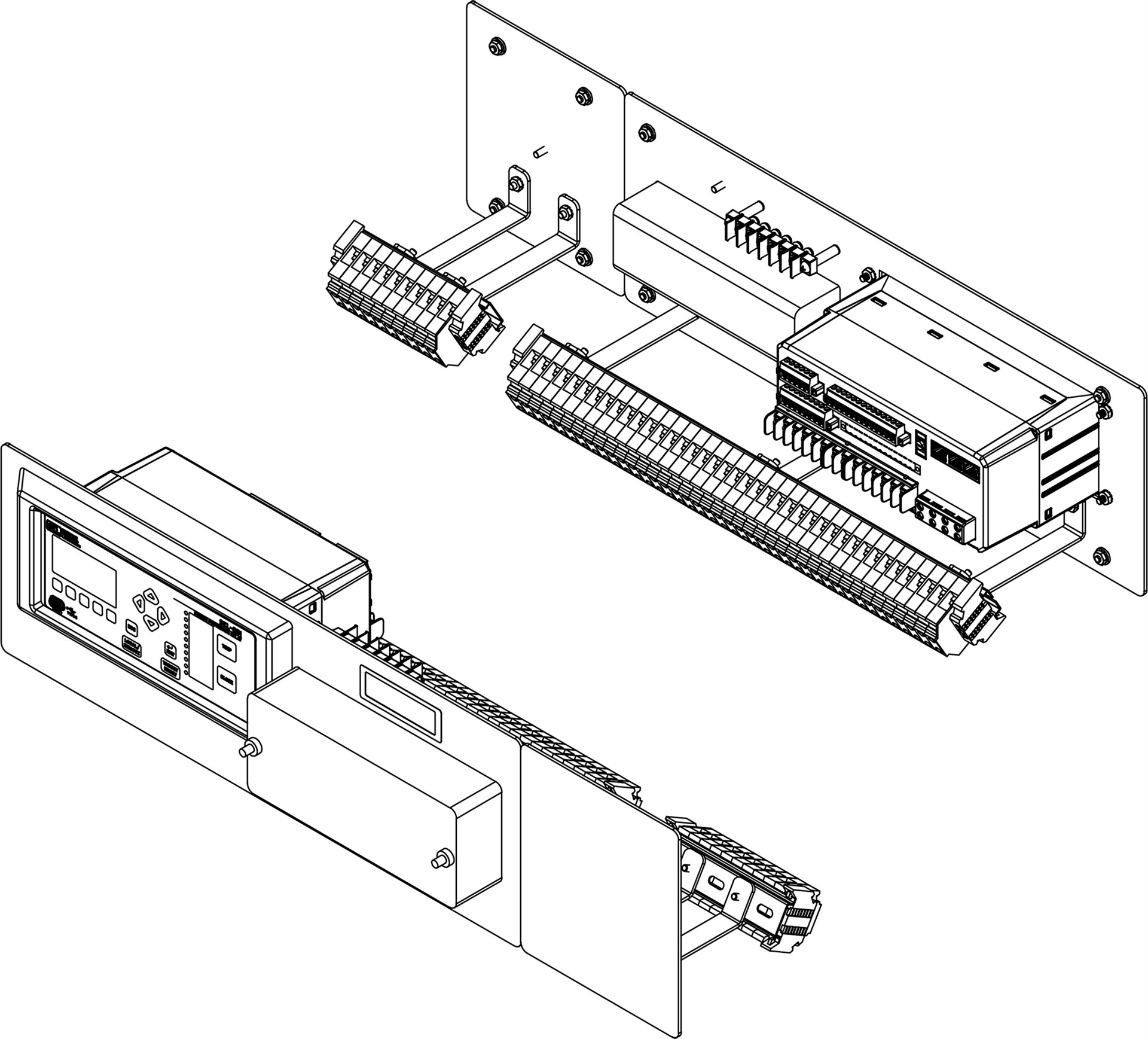
-
-
- 1
SEL-787Z
- 2
SEL-HZM
- 3
Relay power, CT, and control terminal blocks
- 4
Relay mounting plate
- 5
Two 14-pole test switches with clear covers
12345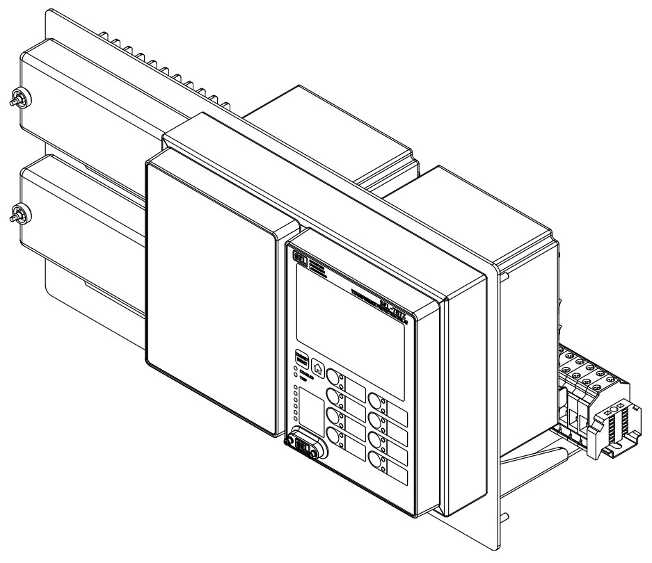
-
Electromechanical Direct-Replacement Assembly Models
Electromechanical Direct-Replacement Assembly Models
Details
The SEL Difference
We use the same world-class manufacturing principles for our direct-replacement assemblies that we use for all our industry-leading products. This allows us to design and test high-quality and comprehensive solutions with reduced delivery times.
Quality
We build a prototype of each new design to create pre-engineered design drawings and document the installation procedure. This process ensures that the design meets functional specifications and enables the manufacturing facility to test and confirm the assembly prior to production.
Application Considerations
Because digital devices have different space and operational requirements than electromechanical relays and relay and panel wiring methods vary, consider these factors when planning a direct-replacement assembly installation.
If these parameters do not work for your application, please contact SEL Engineering Services. We are happy to discuss a custom assembly design to meet your needs.
Panel and Relay Configuration
Existing sets of three single-phase electromechanical relays need to be collocated on the same panel and aligned horizontally.
- Assemblies accommodate gaps up to 1.25" between relays. Larger spacing may impact overall installation aesthetics.
- Some assemblies accommodate additional neutral or auxiliary function relays. These devices must be located immediately above, below, or beside the three single-phase relays.
Power Supply
A power source for the SEL relay needs to be routed to the direct-replacement assembly. SEL relays accept a wide range of power supply sources, configurable at time of order. Direct-replacement assemblies applied to installations featuring lockout relays can often be powered directly from the lockout relay circuit.
Wiring and Connections
Legacy installations should have the individual outputs from each electromechanical relay shared on common trip buses.
Test switches are C-C style FT configuration with a test plug and jack for each phase and neutral CT.
The Firmware IDs for older versions of the firmware can typically be found in Appendix A of the instruction manual.