Field Experience With Traveling-Wave Protection and Fault Locating
COMED uses SEL-TWFL to pin down fault location
On July 19, 2020, the SEL-T400L Time-Domain Line Protection detected a C-phase-to-ground fault while monitoring a 56.62 mi (91.12 km), 345 kV transmission line between two terminals (referred to as Terminals S and R) on the ComEd system. The SEL-T400L was installed at Terminal S.
Figure 1 shows the voltage and current signals sampled at 1 MHz captured by the SEL-T400L. The single-ended traveling-wave-based fault locator (SE-TWFL) reported the fault location to be 49.266 mi (87.011 percent of the line length) from Terminal S. The traveling-wave directional (TW32) protection element declared the fault in the forward direction in 104 µs, and the incremental-quantity directional (TD32) protection element declared the fault in the forward direction in 1.3 ms. The incremental-quantity distance (TD21) protection element, which was set with a reach of 70 percent of the total line length, correctly restrained.
Upon investigation, the ComEd crew found avian excrement contamination and confirmed the fault location was 49.47 mi (79.61 km) from Terminal S (7.15 mi or 11.51 km from Terminal R). The SE-TWFL result was within one tower span, 0.204 mi (1,077 ft, 328 m) from the actual fault location.
Figure 2 shows the Bewley diagram with the time between the first arriving wave (green cursor) and the expected reflection from the fault (red cursor) being 535.988 µs. Using the equation in (1), which includes the arrival time difference (Δt) and the relay settings for (a) the line length (LL) and (b) the traveling-wave line propagation time (TWLPT), you can manually calculate and confirm the SE-TWFL result to be 49.266 mi (68.019 km) from Terminal S. This result is also available in the information pane of the Bewley diagram in Figure 2. The TWLPT setting of 308 µs was determined by line energization testing during commissioning.
This event confirmed that the SEL-T400L can save time and cost because the crew can be dispatched directly to the faulted tower span without needing to patrol a long section of the transmission line.
Please continue to send user experiences and events related to this technology, or requests for more-detailed information, to TD_Support@selinc.com.
For more details about these specific projects, contact Product Engineer Greg Smelich.
About ComEd
Commonwealth Edison Company (ComEd) provides electric service to more than 4 million customers across northern Illinois, or 70 percent of the state’s population. ComEd is a subsidiary of Exelon Corporation, a leading competitive energy supplier.
NamPower—Dual relays operate for internal fault on 220 kv line in under 1.1 milliseconds
Frans Shanyata of NamPower observes, “There is no doubt from the captured event that this is the fastest protective device in the world.”
On February 4, 2020, a pair of SEL-T400L Time-Domain Line Protection relays detected a C-phase-to-ground fault while monitoring the 70.59 mi (113.6 km), 220 kV overhead transmission line from the Khan to Omburu substations, near Omaruru, Namibia. In addition to the SEL-T400L relays, NamPower applies SEL-311L Line Current Differential Protection and Automation System relays at each terminal that also detected the fault. Figure 1 shows the voltage and current signals sampled at 1 MHz captured by the SEL-T400L at the Omburu substation. It also shows the performance of the SEL-T400L and SEL-311L elements and schemes.
The SEL-T400L relays at Omburu and Khan operated successfully, and relay trip logic was triggered via the independent traveling-wave (TW) differential (TW87) schemes, in 1.09 ms and in 1.05 ms, respectively. The SEL-311L relays at each terminal tripped in 13.87 ms and 35.63 ms. The circuit breaker at each end then cleared the fault in 77.8 ms and 58.5 ms, respectively.
Figure 1 also shows the TW directional forward (TW32F) element asserted in 92 µs, the incremental-quantity directional forward (TD32F) element asserted in 1.09 ms, the TW differential (TW87) scheme asserted in 1.09 ms, and the incremental-quantity ground distance (TD21G) element asserted in 2.59 ms at the Omburu terminal. The SEL-311L made a trip decision in 13.87 ms. This means the SEL-T400L tripped 12.78 ms faster than the SEL-311L.
Figure 2 shows the voltage and current signals recorded at the Khan terminal along with the performance of the SEL-T400L and SEL-311L elements and schemes. TW32F, TD32F, and TW87 elements operated in 47 µs, 1.15 ms, and 1.05 ms, respectively. As expected, TD21G did not assert because the fault occurred beyond the element’s reach.
Figure 3 shows the TWs captured by the SEL-T400L relays at Omburu (black) and Khan (blue). The first TW arrived at the Omburu terminal 239.422 µs before the first TW arrived at the Khan terminal. From this arrival time difference, the relays calculated the fault location as 13.440 mi (21.629 km) from Omburu and 57.148 mi (91.971 km) from Khan using the DE-TWFL method. The TWs recorded at the two terminals are in phase, as we expect for an internal (on-the-line) fault or low-energy event.
The Bewley diagram in Figure 4 shows the time and distance relationship of the current TWs at Omburu (black) and Khan (blue) used for successful DE-TWFL operation for this fault.
The C-phase fault current profiles of both terminals, including the alpha-mode TW currents, are shown in Figure 5. Inspection of these signals reveals two post-fault instances of TW disturbances prior to the fault being cleared. The first instance occurred 37.5 ms after the fault initiated. This disturbance launched TWs that arrived at the Omburu terminal 237.398 µs before arriving at the Khan terminal, with both TWs having positive polarity. This indicates that the disturbance originated at (or near) the same location as the initial fault, helping to confirm the fault location.
The second instance occurred 68.0 ms after the fault initiated and was caused by breaker reignition after the C-phase current was interrupted at the zero crossing. The reignition further delayed fault clearing by 10 ms (half a cycle at 50 Hz) at the Omburu terminal.
As these two event reports confirm, the SEL-T400L relays provided NamPower with the expected ultra-high-speed protection performance at both terminals, fault location within one tower span, visibility of post-fault arcing and circuit breaker reignition, and significantly faster fault-clearing time.
Please continue to send user experiences and events related to this technology, or requests for more-detailed information, to TD_Support@selinc.com.
For more details about these specific projects, contact Product Engineer Greg Smelich.
About NamPower
NamPower, Namibia’s national power utility, was born out of the then South West Africa Water and Electricity Corporation (SWAWEK). SWAWEK was formed on December 19, 1964, as a private and fully affiliated company of the Industrial Development Corporation (IDC) of the Republic of South Africa.
Key to SWAWEK’s success was the effective development of the hydropower station—the Ruacana Scheme—and the establishment of a transmission system for the distribution of electricity through the country’s central districts to Windhoek. Throughout its 32-year history, SWAWEK made a valuable contribution to the country’s economic development. By the early 1980s, the network covered most regions and eventually in 1978, the Ruacana Scheme was energized, with a capacity of 240 MW.
SWAWEK’s last significant act (in association with Eskom) came in May 1996, announcing its intention to construct a 400 kV power line over a distance of 900 km between Aries in Kenhardt in South Africa, via the Kokerboom substation near Keetmanshoop to Auas, near Windhoek. In July 1996, SWAWEK became NamPower.
Red Eléctrica de España Uses Bewley Diagram in Synchrowave Event Software to Obtain DE-TWFL Results
On December 8, 2019, a pair of SEL-T400L Time-Domain Line Protection relays detected an internal B-phase-to-ground fault while monitoring the 61.98 km (38.51 mi), 220 kV, 50 Hz Red Eléctrica de España (REE) overhead transmission line between the Casaquemada and Onuba terminals.
Relay-to-relay communications were not in place, making the double-ended traveling-wave (TW)-based fault location (DE-TWFL) results unavailable for automatic calculation by the relays. However, both relays were connected to a high-accuracy IRIG-B time source. Since the relays were synchronized to absolute time, the DE-TWFL results could be obtained using the Bewley diagram feature in SEL-5601-2synchroWAVeEvent Software.
For this event, the DE-TWFL result was determined to be 27.045 km from the Casaquemada terminal. This was corroborated by the single-ended impedance-based fault location (SE-ZFL) and single-ended TW-based fault location (SE-TWFL) results, which were 24.220 km and 26.728 km, respectively.
The event report data in Figure 1 was used to evaluate the SEL-T400L line protection, which uses elements and schemes based on incremental quantities and TWs. Figure 1 shows the voltage and current signals sampled at 1 MHz by the SEL-T400L at the Casaquemada terminal. The figure also shows the performance of the incremental-quantity directional forward (TD32F) element and incremental-quantity ground distance (TD21G) element, which operated in 1.29 ms and 9.09 ms, respectively. In the SEL-T400L at the Onuba terminal, TD32F and TD21G elements operated in 1.29 ms and 9.69 ms, respectively.
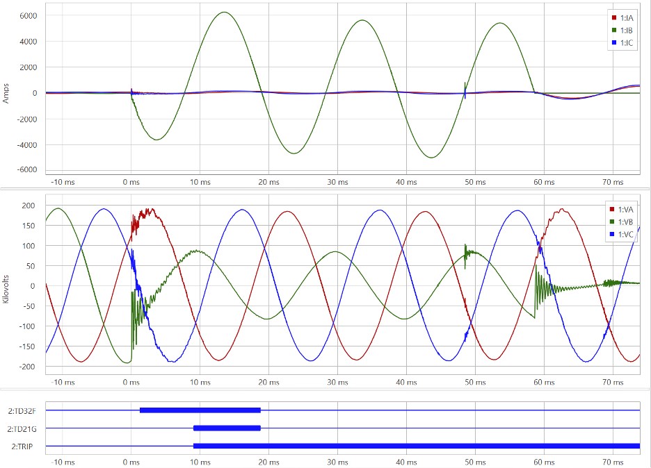
Figure 1 – Casaquemada SEL-T400L event report data showing B-phase fault.
SEL-T400L event reports also contain fault location results for all four methods, including up to four possible SE-TWFL results. Figure 2 shows the fault location results from the SEL-T400L at Casaquemada, and Figure 3 shows the results from the SEL-T400L at Onuba.
[Fault_Location]
SE_TW_Location1,"26.728(km)"
SE_TW_Location2,"33.168(km)"
SE_TW_Location3,"$$$$$$$(km)"
SE_TW_Location4,"$$$$$$$(km)"
DE_TW_Location,"$$$$$$$(km)"
SE_Z-Based_Location,"24.220(km)"
DE_Z-Based_Location,"$$$$$$$(km)"
First_TW_Time_Local,"2019/12/08,05:06:48.182811650"
Figure 2 – SEL-T400L fault location results at Casaquemada
[Fault_Location]
SE_TW_Location1,"3.158(km)"
SE_TW_Location2,"27.738(km)"
SE_TW_Location3,"34.755(km)"
SE_TW_Location4,"38.668(km)"
DE_TW_Location,"$$$$$$$(km)"
SE_Z-Based_Location,"32.081(km)"
DE_Z-Based_Location,"$$$$$$$(km)"
First_TW_Time_Local,"2019/12/08,05:06:48.182838448"
Figure 3 – SEL-T400L fault location results at Onuba.
Since DE-TWFL results were not available for automatic calculation by the relays, REE chose to calculate the results manually using data available in the time-synchronized event reports from both terminals. The “First_TW_Time_Local” value in Figures 2 and 3 indicates the arrival time of the initial TW at each end. These arrival times are compensated for the cable delay between the CTs and the relay. This compensation is performed by back-dating the time stamps through use of the relay settings for CT cable propagation time (TWCPT).
Comparing the “First_TW_Time_Local” value in Figures 2 and 3 shows that the SEL-T400L at Casaquemada was the first to see a TW, which indicates the fault was closer to that terminal. Furthermore, the first TW arrived at Casaquemada 26.798 µs before the first TW arrived at Onuba.
Using the equation in (1), including the arrival time difference (Δt) and relay settings for the line length and traveling-wave line propagation time (LL and TWLPT, respectively), REE calculated the DE-TWFL result to be 27.045 km from Casaquemada. Note that Δt is negative in (1) because the fault was closer to Casaquemada.
Similarly, REE used the equation in (1) to calculate the fault location from the Onuba terminal. Since the fault was closer to Casaquemada, Δt is a positive number when performing the calculation with respect to Onuba, and the result is 34.935 km.
Figure 4 shows the TWs captured by the SEL-T400L relays at Casaquemada (black) and Onuba (blue) and displays the relative arrival time difference between the TWs at each end. The arrival time difference in Figure 4 (–27.037 µs) differs from the value determined previously (–26.798 µs) because it does not compensate for CT cable delay (TWCPT setting in each relay). When compensation for TWCPT is applied to Figure 4, the same arrival time difference is obtained: –27.037 – (0.238 – 0.477) µs = –26.798 µs. Figure 4 also shows that both TWs are in phase (i.e., both have negative polarity), as we expect for an internal (on-the-line) event or fault.
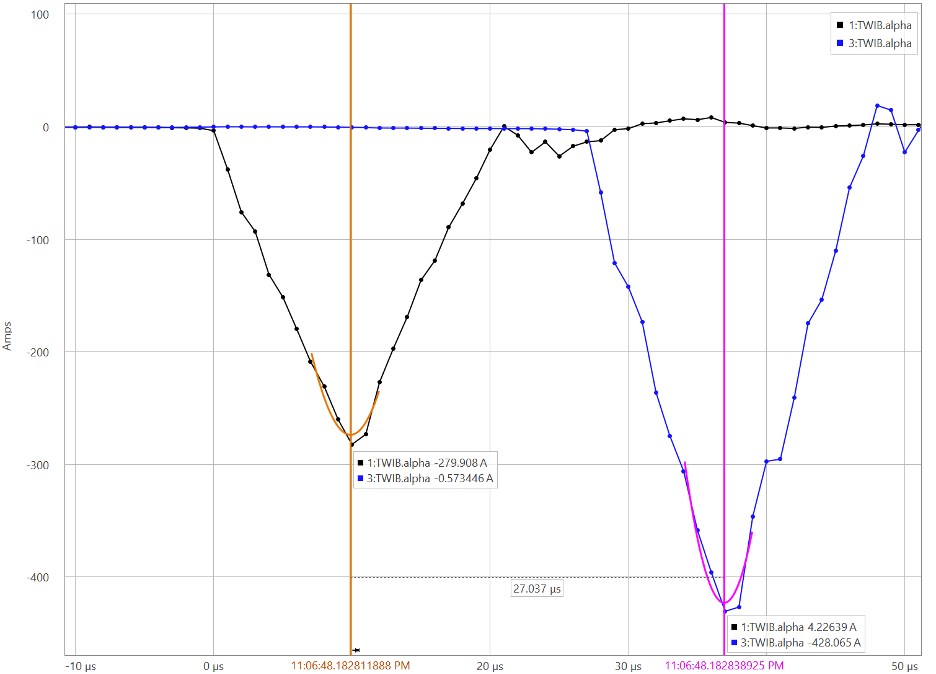
Figure 4 – SEL-T400L oscillograph data showing B-phase Casaquemada (black) and Onuba (blue) TWs.
The Bewley diagram in Figure 5 shows the time and distance relationship of the measured B-phase alpha-mode TW currents for the Casaquemada (black) and Onuba (blue) terminals with subsequent reflections. The fault location provided by the software matches the result of the manual calculations using the equation in (1).
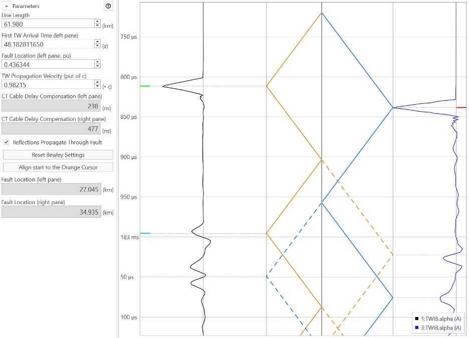
Figure 5 – Bewley diagram showing the measured B-phase alpha-mode TW currents for the Casaquemada (black) and Onuba (blue) terminals.
The offline DE-TWFL results calculated by REE differed from the SE-TWFL results in Figures 2 and 3 by 317 m (1,040 ft) and 180 m (591 ft), respectively. The SE-TWFL and SE-ZFL results corroborated the DE-TWFL results REE obtained from the Bewley diagram in synchroWAVe Event and by manual calculation.
Armed with the results of this analysis, REE’s maintenance team inspected the circuit and found evidence of the fault at a tower located 26.942 km from Casaquemada (35.009 km from Onuba). Identification of the true fault location confirmed that the results obtained from the Bewley diagram in synchroWAVe Event and from manual calculation of the DE-TWFL were within one tower span from either end: 103 m from Casaquemada and 74 m from Onuba.
Please continue to send user experiences and events related to this technology, or requests for more-detailed information, to TD_Support@selinc.com.
For more details about these specific projects, contact Product Engineer Greg Smelich.
About REE
Red Eléctrica de España is the transmission grid owner and operator for the transmission system in Spain. With more than 44,000 km of high-voltage transmission lines, REE is responsible for ensuring the proper operation of the Spanish electrical system, coordinating the generation transport system and planning the long-term growth of the transmission network to provide secure and continuous power supply to the country.
Petroeléctrica de los Llanos (PEL) benefits from the excellent performance of the SEL-T400L relays
On August 1, 2019, a pair of SEL-T400L Time-Domain Line Protection relays detected a C-phase-to-ground fault while monitoring the 153.2 km (95.2 mi) 230 kV PEL transmission line from Jagüey to Quifa. This line is part of the 260 km (161.6 mi) 230 kV PEL transmission corridor from Chivor to Rubiales in Northeast Colombia, shown in Figure 1. The fault was induced by lightning that caused an insulator flashover.
An SEL-421 Protection, Automation, and Control System primary line protection relay at each terminal detected the flashover fault event. Both relays tripped the C-phase circuit breaker pole via the Zone 1 ground distance (Z1G) element and then successfully reclosed. The Jagüey SEL-421 relay tripped (Z1G asserted) in 23 ms, and the circuit breaker opened 18.5 ms later (total of 41.5 ms), as shown in Figure 2. The line was reclosed in 1.36 s and 1.49 s from the Quifa and Jagüey terminals, respectively.
The SEL-T400L relays monitoring the line at each terminal recorded the flashover fault event. Figure 3 shows the 1 MHz high-resolution currents and voltages captured by the SEL-T400L.
Figure 4 shows the traveling waves (TWs) captured by the SEL-T400L relays at Jagüey (black) and Quifa (blue). We observe that the first TW arrived at Jagüey terminal 105.548 µs before the first TW arrived at Quifa terminal. The TWs recorded at the two terminals are in phase, as we expect for an internal (on the line) event or fault.
The SEL-T400L relays used the DE-TWFL method to calculate the distance to the fault as 60.995 km from Jagüey and 92.175 km from Quifa.
Based on the SEL-T400L fault location, the PEL patrol crew started inspecting the line at transmission tower 320, located 61.025 km from Jagüey. They then inspected tower 321, located at 61.501 km, and noticed the damaged C-phase insulator shown in Figure 5. The SEL-T400L-reported location is 506 m (1,660 ft) beyond the patrol crew-reported fault location, which is just over one tower span! Figure 6 shows the new insulator.
To evaluate the SEL-T400L line protection, which uses incremental-quantity and TW elements, the event report data in Figure 7 shows the voltage and current signals sampled at 1 MHz by the SEL-T400L at the Jagüey terminal. The figure also shows the performance of the TW directional (TW32) element, incremental-quantity directional (TD32) element, TW differential (TW87) element, POTT scheme, and incremental-quantity distance (TD21) element, which operated in 69 µs, 1.37 ms, 1.47 ms, 2.17 ms, and 7.67 ms, respectively.
Table 1 compares the SEL-T400L and SEL-421 relay operating times without and with the 18.5 ms circuit breaker time.
As this event report confirms, the SEL-T400L can reduce repair time, improve system stability, and reduce arcing time, leading to an increased likelihood of a successful reclose. Reducing the tripping time improves power quality and reduces the impact of service interruptions.
SEL recommended to PEL that they reconfigure the protection schemes so that the SEL-T400L relays are enabled to trip the circuit breakers for faster tripping and reduced fault duration.
Please continue to send user experiences and events related to this technology, or requests for more-detailed information, to TD_Support@selinc.com.
For more details about these specific projects, contact Product Engineer Greg Smelich.
About PEL
Petroeléctrica de Los Llanos Ltd. is the owner of the transmission corridor that supplies more economical and reliable electricity service to the Rubiales and Quifa fields in the Colombian eastern plains, where it is used for crude oil extraction, treatment, and transportation operations. The presence of PEL in the area has brought oil sector customers of adjacent fields together.
The 260 km (161.6 mi) corridor crosses the departments Boyacá, Casanare, and Meta, from the Chivor substation in the mountains to the Rubiales substation in the eastern plains, via double-circuit transmission towers. The current electric power demand is approximately 140 MW. In route along the corridor are the Jagüey (85 km), Quifa (240 km), and Rubiales (260 km) substations. PEL’s project plans include a future Corocora substation located approximately 185 km from Chivor in the department of Meta.
The 230 kV transmission lines between the Chivor and Quifa substations have SEL-421 relays as the main (primary) and secondary transmission line protection with single-pole tripping and reclosing.
PEL’s customers need the highest electric power service reliability possible for their supply connection to the National Transmission System (NTS) via the PEL transmission network. The high isoceraunic (thunderstorm) activity during the rainy season along the 260 km corridor can result in lightning discharge currents as high as 200 kA, which increases the risk of service interruptions due to insulator surface flashovers and failures. To facilitate the accurate location of faults, which impedance-based fault location cannot provide, PEL has installed two SEL-T400L relays on the line section from Jagüey to Quifa.
Single-ended traveling-wave-based fault locator in SEL-T400L pinpoints location of fault induced by sUAS
On June 21, 2019, an SEL-T400L Time-Domain Line Protection detected a C-phase-to-A-phase fault while monitoring a 16.6 km, 115 kV transmission line from Puebla Dos to Amozoc, northeast of Puebla, Mexico. The fault was induced by a small unmanned aerial system (sUAS), commonly known as a drone.
The event report in Figure 1 shows the voltage and current signals (sampled at 1 MHz) recorded by the SEL-T400L at the Puebla Dos terminal. Figure 1 also shows the performance of the incremental-quantity distance (TD21) protection element, which operated in less than 3.5 ms (assertion of the TD21CA Relay Word bit).
The single-ended traveling-wave-based fault locator (SE-TWFL) in the SEL-T400L reported the fault location to be 7.336 km from the Puebla Dos terminal.
On investigation, the crew found the charred remains of the sUAS between tower 31 (7.41 km from the local terminal) and 32 (7.66 km from the local terminal), which has a 250-meter span. The photographs in Figure 2 and Figure 3 show charred parts of the sUAS still suspended on the phase conductors and on the ground beneath, respectively. The identification of the fault between towers 31 and 32 confirms that the SE-TWFL result is between 74 and 324 meters (243 to 1,063 feet) from the actual location.
As this event report confirms, the SEL-T400L relay can help save time and cost, since the crew can be dispatched directly to the faulted tower span without needing to patrol a long section of the transmission line.
Want to learn more about the accurate fault-locating capabilities of the world’s fastest relay? Check out the upcoming APP T400L SEL University course at our Pullman, Washington, headquarters.
Please continue to send user experiences and events related to this technology, or requests for more-detailed information, to TD_Support@selinc.com.
For more details about these specific projects, contact Product Engineer Greg Smelich.
SEL-T400L Field Report: Forest Fire in Colombia Initiates B-Phase-to-Ground Fault
CELSIA, an electric company that operates in Colombia, Panama, and Costa Rica, reported that a forest fire caused a B-phase-to-ground short-circuit fault on a 115 kV transmission line. CELSIA had installed two SEL-T400L Time-Domain Line Protection devices on the 64.34 km (39.97 mi) transmission line with point-to-point fiber-optic communications between the two substations. The transmission line crosses the Colombian forest, and it often takes weeks to locate faults in the remote, fire-prone forest, so CELSIA hoped the SEL-T400L devices would help pinpoint fault locations. CELSIA wanted to verify the accuracy of the fault-locating method and also test the innovative SEL-T400L time-domain and traveling-wave protection functions to analyze their performance versus traditional protection.
On September 11, 2018, a forest fire burned through a 13.2 kV distribution line wooden pole near a 115 kV transmission line. The downed pole caused the extra sag distribution line span that crossed under the transmission line to be pulled tight under the additional tension. When the normally extra sagging distribution line span was raised under tension by the downed pole in an adjacent span, the distribution conductors came too close to the transmission line above, resulting in a B-phase-to-ground fault on the transmission line. The fault was promptly detected by the two SEL-T400L devices, which then operated. Local inhabitants reported observing explosions at the fault location caused by the arcing intercircuit fault between the live distribution and transmission circuits.
CELSIA engineers confirmed the fault location provided by the SEL-T400L devices, with accuracy within 300 m.
Figure 2 shows the SEL-T400L traveling-wave differential (TW87) scheme operated in 0.62 ms. The directional elements, TW32 and TD32, reported a forward direction (TW32F and TD32F asserted) and operated in 120 µs and 1.32 ms, respectively. The ground time-domain distance element (TD21G) operated in 6.72 ms.
The SEL-T400L double-ended traveling-wave fault locator (DE-TWFL) reported the location as 16.494 km. The SEL-T400L single-ended traveling-wave fault locator (SE-TWFL) reported the location as 16.373 km. The line patrol confirmed the fault location was within 300 meters (less than one pole span) of the DE-TWFL location. In Figure 3, the Bewley lattice diagram shows the time and distance relationship of the local and remote traveling-wave currents for successful DE-TWFL and SE-TWFL operations for this fault. The first traveling waves seen at both terminals (light green and red markers) provided both relays the information to calculate the DE-TWFL, and the clear reflection at the local terminal (cyan marker) provided the local relay the information to calculate the SE-TWFL.
Figure 3 – Bewley lattice diagram of traveling-wave local and remote currents recorded in the local SEL-T400L.
About CELSIA
CELSIA is part of the conglomerate Grupo Argos that has 28 generation plants with a total capacity of 2.4 GW. CELSIA’s consumer electric services are offered through a local Colombian utility called EPSA (Empresa de Energía del Pacífico S.A.). EPSA’s network has 6 hydroelectric power plants, 84 substations, 20,473 km of distribution lines, and 291 km of transmission lines. EPSA provides electricity to more than 600,000 customers in the regions of Valle del Cauca, Cauca, and Tolima.
Please continue to send user experiences and events related to this technology, or requests for more-detailed information, to TD_Support@selinc.com.
For more details about these specific projects, contact Product Engineer Greg Smelich.
SEL-T400L Traveling-Wave Differential Scheme Operates in Less Than a Millisecond
On July 20, 2018, SEL-T400L Time-Domain Line Protection installed on an 8.49-mile, 69 kV transmission line in Arizona operated for a human-induced internal C-phase-to-ground fault. The fault was caused by a foil balloon melting across the C-phase wood-pole-mounted insulator, from the phase conductor to the bare pole ground conductor.
The SEL-T400L traveling-wave differential (TW87) scheme operated in 0.91 ms, and the ground time-domain distance element (TD21G) operated in 2.81 ms. Using the double-ended traveling-wave (TW) fault-locating method, the SEL-T400L located the fault within 111 feet of the actual fault location (shown in Figure 1).
Figure 2 shows the voltages and currents captured by the SEL-T400L at one end of the line, along with the protection elements.
Figure 3 is the Bewley lattice diagram showing the time and distance relationship of the measured C-phase alpha-mode TW currents for the local (black) and remote (blue) terminals with subsequent reflections. The double-ended TW fault locator uses the arrival time of the first traveling wave at each end to accurately calculate the fault location.
Please continue to send user experiences and events related to this technology, or requests for more-detailed information, to TD_Support@selinc.com.
For more details about these specific projects, contact Product Engineer Greg Smelich.
External Fault Validates Security of SEL-T400L Protection Schemes
On July 9, 2018, an electric utility in New Mexico, USA, reported a fault behind the east terminal of a 345 kV, 33.1 mi transmission line. This fault triggered event reports in the SEL-T400L Time-Domain Line Protection devices protecting the line. These devices are applied with traveling-wave differential (TW87), incremental-quantity distance (TD21), and permissive overreaching transfer trip (POTT) schemes enabled to trip the circuit breakers. The directional elements in the SEL-T400L at the east terminal declared a reverse fault, restraining the operation of the POTT scheme. The TW87 scheme and underreaching distance element were also restrained for this external fault.
Figure 1 shows the captured oscillographic data at the east terminal. The directional elements, TW32 and TD32, reported a reverse fault.
Figure 2 shows the C-phase alpha-mode traveling-wave (TW) currents for the east terminal (black) and west terminal (blue), with subsequent reflections, for when the first TW enters the protected transmission line (first black peak), continues along the protected line, and exits the protected transmission line (first blue peak). The interval between the first TWs that arrived at the two terminals is the TW line propagation time (TWLPT). The polarities of these waves are opposite, indicating an external fault. The TWLPT is 186.317 µs, which shows a difference of 1.273 µs compared with the expected TWLPT (corresponding to the SEL-T400L TWLPT setting) of 187.59 µs.
The TWLPT setting of 187.59 µs was determined by line energization testing during commissioning. As this event report shows, external fault event reports can help further refine the TWLPT setting.
Please continue to send user experiences and events related to this technology, or requests for more-detailed information, to TD_Support@selinc.com.
For more details about these specific projects, contact Product Engineer Greg Smelich.
SEL-T400L POTT Scheme Operates in 1.3 ms When Lightning Strikes a Transmission Line in Hawaii
On April 15, 2018, the SEL-T400L Time-Domain Line Protection devices monitoring a 16.75-mile transmission line in Hawaii detected an internal three-phase fault caused by a lightning strike. Each terminal of the line has an SEL-T400L and an SEL-311L Line Current Differential Protection and Automation System, with the protection systems sharing a single direct-fiber channel using wavelength division multiplexer (WDM) couplers. Figure 1 shows the passive WDM couplers where the two wavelengths, 1,550 nm and 1,310 nm, are multiplexed on the transmitted path and demultiplexed on the receiving path. The WDM approach allows the SEL-311L data exchange to coexist with the real-time sharing of the 1 MHz data required by the traveling-wave differential scheme and double-ended fault-locating functions in SEL-T400L devices.
The SEL-T400L POTT scheme operated in 1.30 milliseconds, as shown in Figure 2. The SEL-T400L double-ended traveling-wave fault locator (TWFL) reported the location at 11.279 miles. We typically expect the TWFL to report a location result within 1,000 feet (300 m).
Please continue to send user experiences and events related to this technology, or requests for more-detailed information, to TD_Support@selinc.com.
For more details about these specific projects, contact Product Engineer Greg Smelich.
SEL-T400L Operates in 2 ms on a 161 kV Transmission Line
In April and May of 2018, the SEL-T400L Time-Domain Line Protection showcased its speed for detecting internal faults on a 72.8 mile, 161 kV transmission line in Idaho. The SEL-T400L installed at one of the terminals recorded four line-to-ground faults. The average operating time of the ground time-domain distance element (TD21G) was 1.59 milliseconds—less than 1/8 of a power system cycle at 60 Hz!
The first event is shown in Figure 1. This is a Phase-C-to-ground fault for which the directional elements, TW32 and TD32, asserted in 115 µs and 1.12 ms, respectively. The SEL-T400L made a trip decision based on the TD21G element in 1.62 ms—this is before the fault current even gets halfway to the first peak!
Table 1 shows the operating times of the directional elements, TW32 and TD32, and the ground distance element, TD21G, for all four events.
Please continue to send user experiences and events related to this technology, or requests for more-detailed information, to TD_Support@selinc.com.
For more details about these specific projects, contact Product Engineer Greg Smelich.
SEL-T400L Successful Operation for a Challenging Evolving Fault
On December 13, 2017, SEL-T400L Time-Domain Line Protection devices installed in a permissive overreaching transfer trip (POTT) scheme on a 230 kV, 28.4 km transmission line in Central America selectively tripped Pole C for an internal C-phase-to-ground fault. The SEL-T400L devices then tripped Poles A and B when the scheme detected a subsequent internal C-phase-to-A-phase-to-ground fault with Pole C already open.
This sound multiple-pole tripping performance demonstrates the flawless operation of the SEL-T400L protection scheme for two separate faults that occurred less than 155 ms apart.
The SEL-T400L POTT scheme tripped east-terminal Pole C in 2.5 ms and west-terminal Pole C in 2.2 ms after detecting the internal C-phase-to-ground fault. For the subsequent evolving fault that occurred 154.8 ms later, the POTT scheme tripped west-terminal Poles A and B in 2.7 ms and east-terminal Poles A and B in 2.6 ms. You can observe these durations in Figure 1 above for the west-terminal SEL-T400L.
Please continue to send user experiences and events related to this technology, or requests for more-detailed information, to TD_Support@selinc.com.
For more details about these specific projects, contact Product Engineer Greg Smelich.
First SEL-T400L Operation in Central America!
On December 8, 2017, SEL-T400L Time-Domain Line Protection devices installed on a 230 kV, 28.4 km transmission line in Central America tripped for an internal C-phase-to-ground fault, marking the first successful field operation of the SEL-T400L in Central America.
SEL’s time-domain protection and fault-locating technology is exceptional. The TW87 protection scheme in the remote SEL-T400L operated in 1.01 ms. At the local end, the TW87 scheme operated in 1.08 ms. You can view the TW87 scheme operating times in Figure 1 below. The local directional elements, TW32 and TD32, asserted in 0.11 ms and 2.11 ms, respectively.
Figure 1 shows the remote (blue) and the local (black) current traveling waves along with the protection scheme outputs from both terminals.
Figure 2 is a Bewley lattice diagram showing the time and distance relationship of the local and remote traveling-wave currents with subsequent reflections.
Please continue to send user experiences and events related to this technology, or requests for more-detailed information, to TD_Support@selinc.com.
For more details about these specific projects, contact Product Engineer Greg Smelich.
Traveling-Wave Differential Operation on a 115 kV Transmission Line
SEL-T400L Time-Domain Line Protection devices installed on a 115 kV transmission line in Maryland operated for an internal A-phase-to-ground fault last month. The SEL-T400L fault locator reported the location as just over 2 feet from the actual fault location. In this event, the TW87 protection scheme operated in 1.03 ms and the Zone 1 underreaching distance (TD21) element operated in 6 ms. Figure 1 shows the voltages and currents captured by the SEL-T400L along with the protection elements.
The actual distance to the fault was 4.5516 miles from the substation. The SEL-T400L double-ended traveling-wave fault locator (DE-TWFL) reported the location as 4.552 miles (see Figure 2 for the Bewley lattice diagram, showing the time and distance relationship of the local and remote traveling-wave currents). The SEL-T400L single-ended traveling-wave fault locator (SE-TWFL) reported the location as 4.586 miles, within 182 feet of the actual fault. We typically expect the TWFL to report a result within 1,000 feet (305 m), or about one tower span.
These results show the operation of millisecond time-domain protection, traveling-wave fault locating technology, and a megahertz sampling view of system performance. We can now view phenomena such as breaker restrikes, self-extinguishing faults and their locations, and perhaps occurrences we haven’t thought of yet. The benefits are lower maintenance costs, less damage, better and faster understanding and improvements, and more-reliable service.
Please continue to send user experiences and events related to this technology, or requests for more-detailed information, to TD_Support@selinc.com.
For more details about these specific projects, contact Product Engineer Greg Smelich.
Seeing the Power System With New Eyes: Real-World Event Reports From the SEL-T400L
Dear SEL customers and friends:
It has been over a year since we introduced our ultra-high-speed transmission line protective relay—the SEL-T400L Time-Domain Line Protection—with highly accurate fault-locating technology and a one-megahertz sampling rate fault recorder. Many of you have installed the SEL-T400L in pilot installations and are sending us event reports triggered on various disturbances and faults. We appreciate your vested interest in exploring and adopting new technologies. I am happy to share that the performance of the SEL-T400L in these pilot installations is meeting and exceeding our expectations.
This event below is from a 230 kV, 28.4 km transmission line where the SEL-T400L issued the trip command in one millisecond using a traveling-wave differential scheme (TW87)—this is unheard of! The traditional phasor-based distance relay operated in 20 ms for this event.
Events from numerous installations across the world demonstrate both the speed and security of our ultra-high-speed line protection system.
Customers see value in the accurate fault-locating functions of the SEL-T400L. Locating faults faster and addressing the damage will reduce recurring faults, improving the reliability of the power system. Because this technology is affordable and easy to use, we envision every transmission line will be configured with a traveling-wave fault-locating system in the near future.
The one-megahertz fault-recording capability in the SEL-T400L is exceptional, allowing customers to detect breaker restrikes using these event records. Some of the events captured show sustained high-frequency transients during normal load conditions. We are working with customers to understand the root cause of these events; it is educational, informative, intriguing, and FUN!! We are seeing power systems with new eyes.
Our SEL-T400L team will be sharing more field results with you in the upcoming months, and I trust you will find them valuable as well. I encourage all of you to take advantage of the latest innovation in the field of power system protection and be part of this technology. Please share your ideas and thoughts on the role that traveling-wave techniques and the SEL-T400L can possibly play as you implement next-generation solutions to transmission line protection. Our own SEL protection subject-matter experts and application engineers are at your service for guidance.
Best regards,
Ed
Other user experiences
Learn more